Water cleaning device for water valve

A technology of cleaning device and water valve, which is used in drying gas arrangement, static material dryer, local stirring dryer, etc. Fast speed, quality assurance, high efficiency

Active Publication Date: 2018-05-25
创意塑胶工业(苏州)有限公司
View PDF4 Cites 0 Cited by
  • Summary
  • Abstract
  • Description
  • Claims
  • Application Information

AI Technical Summary

Problems solved by technology

[0002] After the water valve is tested with water, the water in the water valve needs to be drained. The existing operation is to manually shake the water in the water valve, trying to clean the water in the water valve. Not only is it difficult to control the residual water, but also the labor intensity is extremely high. Big, an ordinary employee can only process 20-25 products per hour, and often because the water is not drained, it is complained after being shipped abroad

Method used


Image

  • Water cleaning device for water valve

Examples


Embodiment Construction

[0027] The specific implementation manners of the present invention will be further described below in conjunction with the drawings and examples. The following examples are only used to illustrate the technical solution of the present invention more clearly, but not to limit the protection scope of the present invention.

[0028] The technical scheme of concrete implementation of the present invention is:

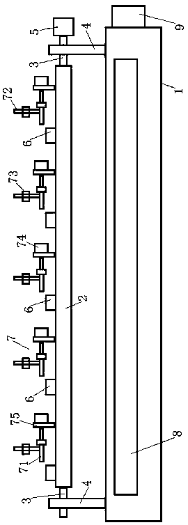
[0029] Such as figure 1 As shown, a water cleaning device for a water valve includes a flat frame 1;

[0030] A flat rectangular support plate 2 is arranged above the frame 1;

[0031] The two ends of the support plate 2 in the length direction are respectively connected with a flat rotating shaft 3, which are respectively connected to the two ends of the support plate 2 in the length direction.

[0032] A shaft seat 4 is fitted on the outer periphery of each rotating shaft 3, and the shaft seat 4 is fixed on the frame 1;

[0033] The support plate 2 is supported by tw...


PUM


Abstract

The invention discloses a water removing device of water valves. The water removing device comprises a horizontally arranged rack, wherein a horizontally arranged rectangular support plate is arranged above the rack; a horizontally arranged rotating shaft is connected at each of the two ends of the support plate in the length direction; a shaft seat is mounted on the periphery of each rotating shaft in a sleeving manner; the shaft seats are fixed to the rack; one of the rotating shafts is equipped with a driving motor used for driving the rotating shaft to rotate around the self axis; a plurality of fixtures used for clamping the water valves are fixed to the support plate; each fixture is equipped with an air blowing device used for blowing air to liquid input ends of the water valves; a water collection tank is arranged right below the support plate; and the water collection tank is arranged in the length direction of the support plate. According to the water removing device of the water valves, water in the water valves can be drained, batch treatment can be achieved, the efficiency is high, an air blowing manner is adopted, the blow-drying speed is high, the water valves are not damaged, and the quality of the water valves can be guaranteed.

Description

technical field [0001] The invention relates to a water cleaning device for a water valve. Background technique [0002] After the water valve is tested with water, the water in the water valve needs to be drained. The existing operation is to manually shake the water in the water valve, trying to clean the water in the water valve. Not only is it difficult to control the residual water, but also the labor intensity is extremely high. Big, an ordinary employee can only process 20-25 products per hour, and often complains after the water is not drained and shipped abroad. Contents of the invention [0003] The purpose of the present invention is to provide a water cleaning device for a water valve, which can drain the water in the water valve. [0004] In order to achieve the above object, the technical solution of the present invention is to design a water cleaning device for a water valve, including a flat rack; [0005] A flat rectangular support plate is arranged abov...

Claims


Application Information

Patent Timeline
Patent Type & Authority Patents(China)
IPC IPC(8): F26B9/10F26B21/00
CPCF26B9/10F26B21/004
Inventor 林国汉
Owner 创意塑胶工业(苏州)有限公司
Why Eureka
Try Eureka