Track vibration reduction fastener with high transverse stability and rigidity changing method thereof

A lateral stability and vibration damping fastener technology, applied in the field of rail vibration damping, can solve the problems of reduced service life of rails, poor lateral stability, limited lateral stiffness, etc. Effect of low dynamic-static stiffness ratio

Pending Publication Date: 2022-06-24
ZHUZHOU TIMES NEW MATERIALS TECH
View PDF9 Cites 0 Cited by
  • Summary
  • Abstract
  • Description
  • Claims
  • Application Information

AI Technical Summary

Problems solved by technology

Among them, the disadvantage of the compression type damping fastener is that the vertical stiffness is relatively large, and the vibration damping effect is limited; the disadvantage of the shear type vibration damping fastener is that the vertical stiffness is small, and the vibration damping effect is good, but the lateral stiffness is limited. The lateral stability is not good, and the above-mentioned corrugation phenomenon is prone to occur, which will reduce the service life of the rail

Method used


Image

  • Track vibration reduction fastener with high transverse stability and rigidity changing method thereof
  • Track vibration reduction fastener with high transverse stability and rigidity changing method thereof
  • Track vibration reduction fastener with high transverse stability and rigidity changing method thereof

Examples


Embodiment 1

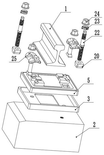
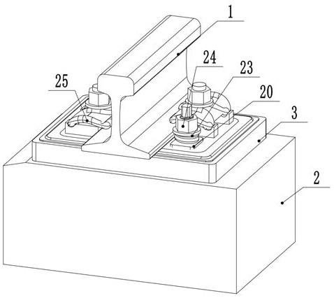
[0042] A rail damping fastener with high lateral stability, such as figure 1 As shown, it includes a rail damper 5 located at the lower end of the rail 1 and a sleeper 2 located below the rail damper 5. A base support 3 is provided between the rail damper 5 and the sleeper 2, and the base support 3 is fixed on the On the upper end of the sleeper 2, the bottom support 3 includes a accommodating groove 4 with an upward opening; such as figure 2 As shown, the rail damper 5 is limited to the accommodating groove 4 of the bottom support 3, and the bottom support 3 can prevent the rail damper 5 from moving and swaying in the horizontal direction, improving the lateral stability of the damping fastener, preventing Rail 1 is worn. The base support 3 in this embodiment is a rectangular parallelepiped that matches the shape of the rail damper 5 . Those skilled in the art can also set the base support 3 according to the shape requirements of the rail damper 5 in actual working conditio...

Embodiment 2

[0049] The difference between this embodiment and the first embodiment is that, as Figure 7 As shown, the arrangement and quantity of the large bosses 17 and the small bosses 18 are different from those in the first embodiment. Specifically, the large bosses 17 and the small bosses 18 are evenly spaced on the horizontal row. This embodiment includes three A horizontal row of large bosses 17 and three horizontal rows of small bosses 18 . The non-linear variable stiffness and protection stiffness are formed by the large boss 17 and the small boss 18 .

Embodiment 3

[0051] The difference between this embodiment and the second embodiment is that, if Figure 8 As shown, the shapes of the large bosses 17 and the small bosses 18 are different from those in the second embodiment, and the large bosses 17 and the small bosses 18 in this embodiment are inverted trapezoidal structures.


PUM


Abstract

The invention belongs to the technical field of rail damping, and particularly discloses a rail damping fastener with high transverse stability, which comprises a rail damper arranged at the lower end of a steel rail and a sleeper positioned below the rail damper, and the rail damper is of an integrated metal-rubber composite structure. The rail shock absorber comprises a metal top plate, a metal bottom plate and a rubber vulcanization body, the metal top plate, the rubber vulcanization body and the metal bottom plate comprise a first inverted-cone-shaped side wall, an inverted-cone-shaped rubber vibration isolation peripheral wall and a second inverted-cone-shaped side wall which are matched with one another from inside to outside, and a bottom support is arranged between the rail shock absorber and the sleeper. The rail shock absorber has high transverse stability while having good shock absorption performance, and meanwhile, the non-linear variable rigidity and protection rigidity can be achieved through the rail shock absorber.

Description

technical field [0001] The invention relates to a rail vibration damping fastener with high lateral stability and a method for changing stiffness thereof, belonging to the technical field of rail vibration damping. Background technique [0002] In recent years, with the rapid development of my country's social economy and the acceleration of urbanization, rail transportation systems such as subways, high-speed rail, and urban rail have developed rapidly. Common vibration damping fasteners are usually provided under the rails of rail transportation systems to reduce the vibration and noise of the rails when the rail vehicles are running. In practical applications, in order to further reduce the sound pollution caused by the rail transportation system and improve the comfort of passengers , More and more track lines use high-elasticity damping fasteners to replace ordinary fasteners under the rails. [0003] Since the high elastic vibration damping fastener greatly reduces th...

Claims


Application Information

Patent Timeline
Patent Type & Authority Applications(China)
IPC IPC(8): E01B9/02E01B9/54E01B9/58E01B9/62E01B9/68E01B19/00
CPCE01B9/02E01B9/54E01B9/58E01B9/62E01B9/683E01B9/685E01B19/003
Inventor 欧阳斌刘韦邓娇陈国平颜湘龙辉鲍鸣张淑芳王一毫何正宏
Owner ZHUZHOU TIMES NEW MATERIALS TECH
Why Eureka
Try Eureka