
Carton manufacturing and conveying device

A conveying device and carton technology, applied in transportation and packaging, box making operations, packaging, etc., can solve problems such as slipping, cardboard cannot be conveyed, and it is difficult to ensure the delivery of a single piece of cardboard, so as to promote the falling of cardboard and improve the effect of conveying efficiency

Inactive Publication Date: 2022-05-27
江苏互憓通包装有限公司
View PDF10 Cites 0 Cited by
  • Summary
  • Abstract
  • Description
  • Claims
  • Application Information

AI Technical Summary

Problems solved by technology

[0003] Most of the existing conveying devices use the friction between the conveying wheel and the uppermost cardboard to drive the uppermost cardboard to move horizontally, so as to realize the conveyance of a single piece of cardboard. However, in the actual processing process, if the squeeze between the conveying wheel and the cardboard The higher the pressure setting, the greater the friction between the upper cardboard and the lower cardboard. When the conveying wheel transports the upper cardboard, the lower cardboard will also be driven by the upper cardboard to cause horizontal displacement. It is difficult to ensure that only a single piece of cardboard is transported each time. ; If the pressing force between the conveying wheel and the cardboard is set to be small, there will be slippage between the conveying wheel and the cardboard, resulting in the situation that the cardboard cannot be conveyed

Method used


Image

  • Carton manufacturing and conveying device
  • Carton manufacturing and conveying device
  • Carton manufacturing and conveying device

Examples


Embodiment Construction

[0026] The embodiments of the present invention are described in detail below with reference to the accompanying drawings, but the present invention can be implemented in many different ways as defined and covered by the claims.

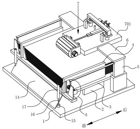
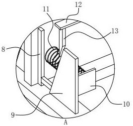
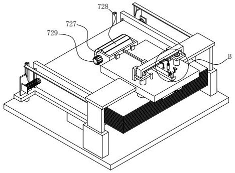
[0027] like figure 1 As shown, the present embodiment provides a carton making and conveying device, comprising a horizontal base plate 1, a plurality of support plates 2 are fixedly installed on the upper surface of the base plate 1, and a horizontal support plate 3 is fixedly installed on the top of the plurality of support plates 2. , the upper surface of the support plate 3 is vertically fixed with two limit plates 4, and the two limit plates 4 are arranged in the front and rear directions, and the upper surface of the bottom plate 1 is located on the left and right sides of the support plate 3. The telescopic plate 5 and the telescopic section end of the electric telescopic plate 5 are fixedly installed with a horizontal lifting plate 6 , and a ...


PUM


Abstract

The invention belongs to the technical field of cartons, and particularly relates to a carton manufacturing and conveying device which comprises a horizontal bottom plate, a plurality of supporting plates are fixedly mounted on the upper surface of the bottom plate, a horizontal bearing plate is jointly and fixedly mounted at the tops of the supporting plates, and two limiting plates are fixedly mounted on the upper surface of the bearing plate. An electric telescopic plate is vertically and fixedly installed on the upper surface of the bottom plate, lifting plates are fixedly installed at the end of the telescopic section of the electric telescopic plate, and a conveying mechanism is installed between the two lifting plates. When cartons are conveyed through the carton conveying device, the conveying mechanism adsorbs the rear end of the uppermost paperboard upwards, so that the uppermost paperboard is inclined, and the edge of the rear end of the uppermost paperboard is pushed through the conveying plate to horizontally convey the uppermost paperboard; by means of the mode, the situation that the lower-layer paperboard is driven due to the fact that the friction force of the upper-layer paperboard piece and the lower-layer paperboard piece is too large is avoided, and meanwhile it is guaranteed that the uppermost-layer paperboard is effectively conveyed.

Description

technical field [0001] The invention belongs to the technical field of carton transportation, in particular to a carton making and conveying device. Background technique [0002] Cardboard boxes are the most widely used packaging products. According to different materials, they can be divided into corrugated boxes, single-layer cardboard boxes, etc., with various specifications and models. In the process of carton making, the square cardboard needs to be cut first to make it into a cross-shaped cardboard, and then the cross-shaped cardboard is folded and pasted. Currently, before cutting the square cardboard, a plurality of cardboards need to be stacked together, and the uppermost layer of cardboard among the plurality of cardboards is conveyed by a conveying device during the production process of the carton. [0003] Most of the existing conveying devices drive the uppermost layer of cardboard to move horizontally through the friction between the conveying wheel and the u...

Claims


Application Information

Patent Timeline
Patent Type & Authority Applications(China)
IPC IPC(8): B31B50/07B31B50/06B31B50/02B31B50/74
CPCB31B50/07B31B50/066B31B50/02B31B50/74Y02W90/10
Inventor 周伟跃
Owner 江苏互憓通包装有限公司
Learn More