a mixing system

A mixing system and mixing tank technology, which is applied to cement mixing devices, clay preparation devices, chemical instruments and methods, etc., can solve problems such as poor water supply and centrifugal pump impeller blockage, and achieve high work efficiency, delicate structure, and easy maintenance. convenient effect

Active Publication Date: 2018-07-20
HUAINAN MINING IND GRP
View PDF6 Cites 0 Cited by
  • Summary
  • Abstract
  • Description
  • Claims
  • Application Information

AI Technical Summary

Problems solved by technology

[0004] The purpose of the present invention is to provide a stirring system to solve the above-mentioned problems in order to solve the defects of centrifugal pump impeller blockage and poor water supply in the prior art.

Method used


Image

  • a mixing system
  • a mixing system

Examples


Embodiment Construction

[0025] In order to have a further understanding and understanding of the structural features of the present invention and the achieved effects, the preferred embodiments and drawings are used in conjunction with detailed descriptions, and the description is as follows:

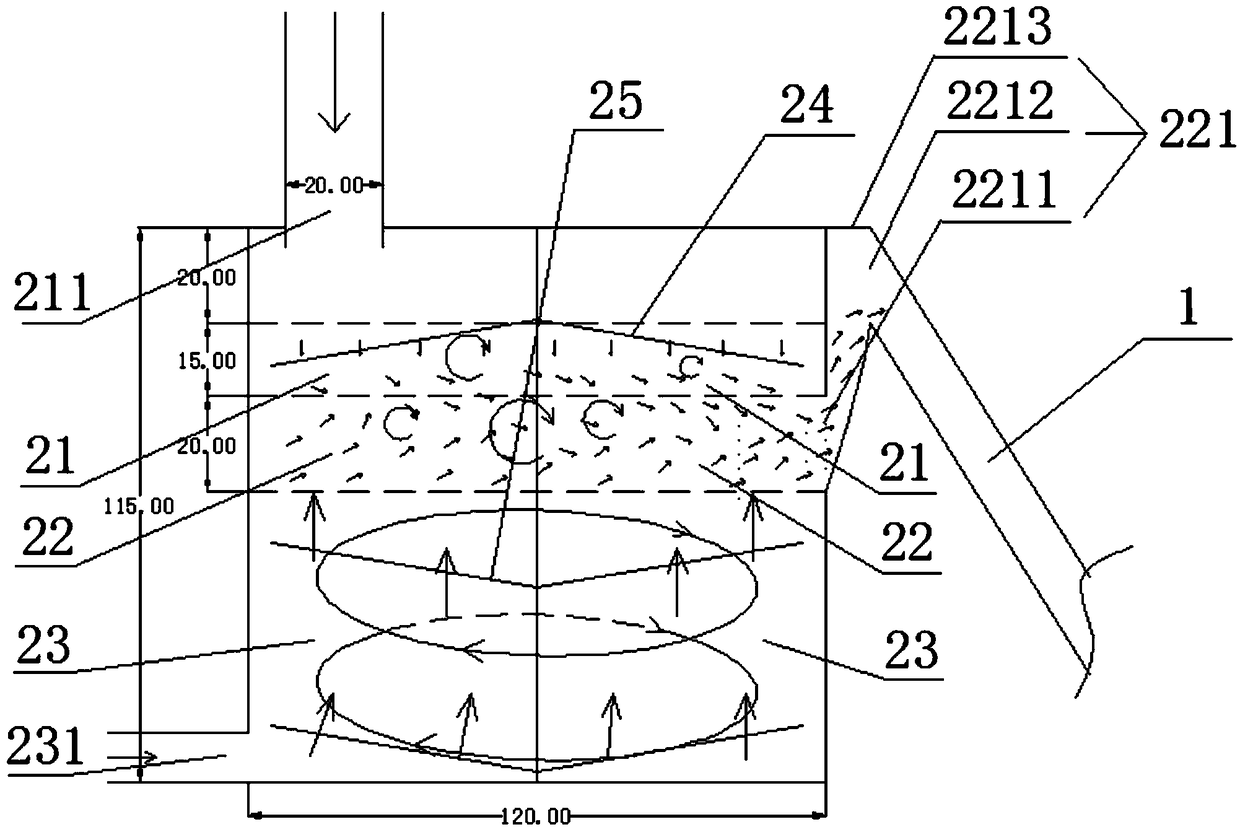
[0026] An automatic pulping system includes a primary stirring device and a secondary stirring device (not shown in the figure); the primary stirring device and the secondary stirring device are connected through a pipeline 1.

[0027] The first-stage mixing device includes a mixing barrel; the height direction of the mixing barrel is divided into a lower ash area 21, a convection mixing area 22, and an upper water area 23 from top to bottom; the top of the lower ash area 21 has a lower ash port 211; a convection mixing area 22 has a slurry outlet 221; the upper water zone 23 has a water inlet 231; in the mixing barrel, there are also multiple sets of stirring fins, and the rotating shafts of the multiple sets of st...


PUM


Abstract

The invention provides a stirring system which comprises a primary stirring device, wherein the primary stirring device comprises a stirring barrel; the stirring barrel is divided into a cement feeding region, a convective mixing region and a water supply region from top to bottom in sequence in a height direction; a cement feeding opening is formed in the top of the cement feeding region; a slurry outlet is formed in the convective mixing region; a water inlet is formed in the water supply region; the water inlet is located on the side wall of the lower end of the stirring barrel; a plurality of groups of stirring fins are arranged in the stirring barrel; rotating shafts of the groups of stirring fins are coaxial; the uppermost group of stirring fins are right-handed spiral fins; the other groups of stirring fins are left-handed spiral fins; the right-handed spiral fins are located in the cement feeding region; and the left-handed spiral fins are located in the water supply region. Compared with the prior art, through the design of the right-handed spiral fins and the left-handed spiral fins in the stirring barrel, the convective mixing region is formed between the right-handed spiral fins and the left-handed spiral fins, and during a rotating process, the right-handed spiral fins accelerate sinking of cement, and the left-handed spiral fins accelerate rising of water, so that deposition of large particles is reduced and a strong convective mixing region is formed near the slurry outlet.

Description

Technical field [0001] The invention relates to the technical field of mining grouting, in particular to a mixing system for manufacturing cement slurry. Background technique [0002] The supporting primary mixing is mainly for grouting projects with small flow, low specific gravity and short grouting duration. [0003] When the proportion of the slurry reaches 1.24 (water-cement ratio 2.5:1) during the pulping process, there will be problems such as blockage of the first-level "mixing tank", dusting and uneven mixing, which cannot meet the requirements of the project for the slurry ratio. ; In addition, after a long time continuous injection of low specific gravity slurry, the centrifugal pump impeller clogged and the water supply is not smooth, etc., which cannot meet the continuous high-intensity grouting requirements. Summary of the invention [0004] The purpose of the present invention is to solve the defects of centrifugal pump impeller blockage and poor water supply in the ...

Claims


Application Information

Patent Timeline
Patent Type & Authority Patents(China)
IPC IPC(8): B28C5/00
CPCB28C5/006
Inventor 李友俊程志忠石德洲苏明金
Owner HUAINAN MINING IND GRP
Why Eureka
Try Eureka