
A construction machinery chassis connection structure
A technology for connecting structures and construction machinery, applied in the substructure, vehicle components, transportation and packaging, etc., can solve the problems of limited bearing capacity, stress concentration, single bearing structure, etc., to achieve high connection reliability, not easy to stress concentration, reduce The effect of welded structures
- Summary
- Abstract
- Description
- Claims
- Application Information
AI Technical Summary
Problems solved by technology
Method used
Image

Examples
Embodiment Construction
[0020] The present invention will be further described below in conjunction with accompanying drawing.
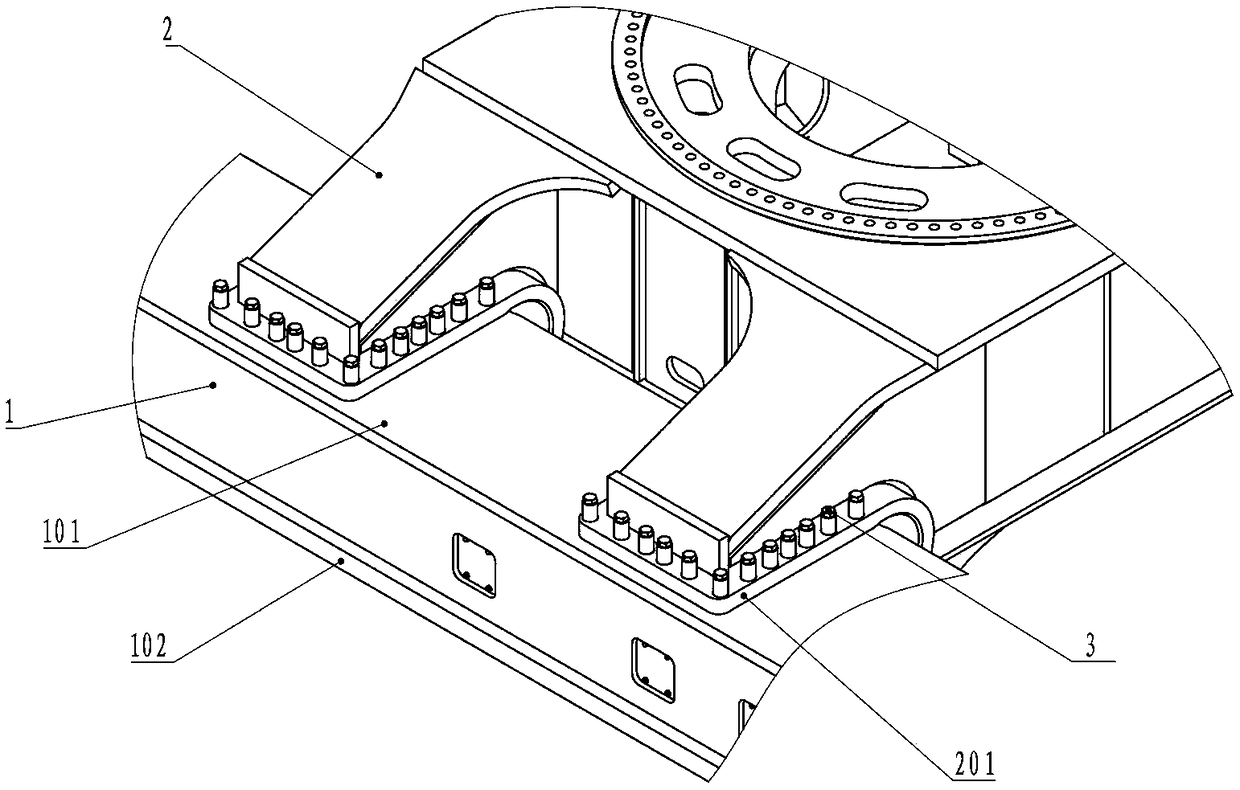
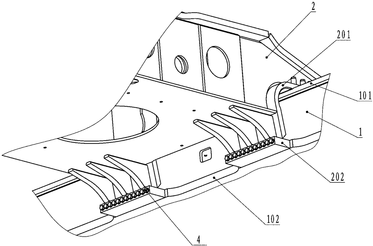
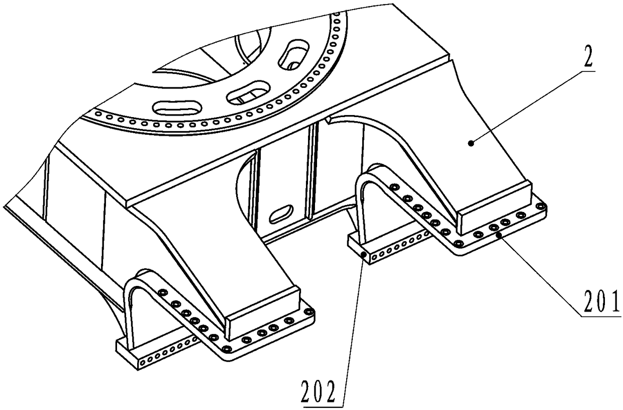
[0021] Such as Figure 1 to Figure 3 As shown, a construction machinery chassis connection structure includes a longitudinal beam 1 and an H frame 2, and also includes an H frame bending connecting plate 201 and an H frame horizontal connecting plate 202 for connecting the H frame 2 to the longitudinal beam 1, and the H frame The frame bending connecting plate 201 and the H frame horizontal connecting plate 202 are welded to form a Z-shaped structure; the H frame bending connecting plate 201 is used as the Z-shaped horizontal folding upper part and the H frame horizontal connecting plate 202 as the Z-shaped horizontal bottom edge The welding is in a Z-shaped structure; the H frame bending connecting plate 201 is welded under one end of the H frame 2; the H frame 2 is fixedly connected with the longitudinal beam top plate 101 of the longitudinal beam 1 through the H frame be...
PUM
 Abstract
Description
Claims
Application Information