Ice melting system for circuit of power distribution network and ice melting method of ice melting system

A distribution network and ice melting technology, which is applied in the installation of overhead lines/cable equipment, electrical components, cables, etc. The formation of ice melting system and other problems can achieve the effect of strong ice melting mobility, improving the ability to resist large-scale rain, snow and freezing disasters, and high ice melting efficiency.

Active Publication Date: 2016-12-07
STATE GRID HUNAN ELECTRIC POWER +2
View PDF4 Cites 9 Cited by
  • Summary
  • Abstract
  • Description
  • Claims
  • Application Information

AI Technical Summary

Problems solved by technology

[0003] At present, there are not many studies on the distribution network ice melting system. The distribution network ice melting devices developed by some scientific research institutes are mainly aimed at melting short lines and ultra-short lines. Carry out partial ice melting, and have not yet formed an ice melting system for a certain area
Moreover, there are many mixed line types in the distribution network, and generally only small cross-section conductors can be deiced, which is difficult
When a large-scale ice disaster occurs, the current configuration of ice melting devices is not enough to support the ice melting of all lines in the distribution network system in this area

Method used


Image

  • Ice melting system for circuit of power distribution network and ice melting method of ice melting system
  • Ice melting system for circuit of power distribution network and ice melting method of ice melting system
  • Ice melting system for circuit of power distribution network and ice melting method of ice melting system

Examples


Embodiment Construction

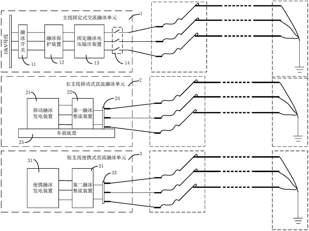
[0031] Such as figure 1 As shown, the distribution network line ice melting system in this embodiment includes a main line fixed AC ice melting unit 1, a long branch line mobile DC ice melting unit 2 and a short branch line portable DC ice melting unit 3, and a main line fixed AC ice melting unit 1 Set in the substation, the main line fixed AC ice melting unit 1 includes an ice melting switch 11, an ice melting protection device 12, a fixed ice melting voltage output device 13, and the input end of the fixed ice melting voltage output device 13 passes through the ice melting protection device 12 in turn 1. The ice-melting switch 11 is connected to the 10kV busbar of the substation, the control end of the ice-melting switch 11 is connected to the ice-melting protection device 12, and the long-branch mobile DC ice-melting unit 2 includes a mobile ice-melting power generation device 21 and a first melting ice-melting unit connected to each other. The ice rectifying device 22 and ...


PUM


Abstract

The invention discloses an ice melting system for a circuit of a power distribution network and an ice melting method of an ice melting system. The system comprises a main line fixed AC ice melting unit, a long branch mobile DC ice melting unit and a short branch portable DC ice melting unit, wherein the main line fixed AC ice melting unit comprises an ice melting switch, an ice melting protection device and a fixed ice melting voltage output device, the long branch mobile DC ice melting unit comprises a mobile ice melting power generation device and a first ice melting rectification device which are connected with each other, and the short branch portable DC ice melting unit comprises a portable ice melting power generation device and a second ice melting rectification device which are connected with each other. The method comprises the step of performing AC ice melting or DC ice melting by selecting different ice melting units according to ice coating conditions and circuit types. Designs are performed according to a main line, a long branch and a short branch, ice melting of all circuits of the power distribution network is covered, the ice melting efficiency of the circuit of the power distribution network can be improved, the ice melting range is expanded, and the capability of resisting rain and snow disaster in a large range by the circuit of the power distribution network is improved.

Description

technical field [0001] The invention belongs to the technical field of electrical engineering, and in particular relates to an ice-melting system and an ice-melting method for distribution network lines. Background technique [0002] Since 2008, the large-scale rain, snow and freezing disasters in the south have caused heavy damage to the power systems of Hunan, Guizhou, Jiangxi, Zhejiang and other provinces. The distribution network lines are the most terminal of electricity sales, and they are widely distributed, mostly in micro-topographic and micro-meteorological areas. The frequent accidents of tower collapse and disconnection have directly affected the reliable power supply of users. The research and design of the distribution network line ice melting system is the key to ensure the reliability of power supply for users during ice disasters. [0003] At present, there are not many studies on the distribution network ice melting system. The distribution network ice mel...

Claims


Application Information

Patent Timeline
Patent Type & Authority Applications(China)
IPC IPC(8): H02G7/16H02G1/02
CPCH02G1/02H02G7/16
Inventor 陆佳政朱远李波谭艳军朱思国周秀冬黄清军
Owner STATE GRID HUNAN ELECTRIC POWER
Why Eureka
Try Eureka