Fire extinguishment warning device for power transformer
What is Al technical title?
Al technical title is built by PatSnap Al team. It summarizes the technical point description of the patent document.
A technology of warning device and transformer, which is applied in fire rescue and other fields, can solve the problems of dangerous operation, low warning force, untimely fire extinguishing, etc., and achieve the effect of strong warning force, timely fire extinguishing and prolonging service life
Inactive Publication Date: 2016-12-21
SHENZHEN CITY FUTIAN DISTRICT SCI & TECH EDUCATION ASSOC FOR JUVENILES
View PDF5 Cites 4 Cited by
Summary
Abstract
Description
Claims
Application Information
AI Technical Summary
This helps you quickly interpret patents by identifying the three key elements:
Problems solved by technology
Method used
Benefits of technology
Problems solved by technology
[0006] In order to overcome the shortcomings of the existing fire extinguishing warning device, such as untimely fire extinguishing, low warning force and dangerous operation, the technical problem to be solved by the present invention is to provide a fire extinguishing warning device for electric power transformers with timely fire extinguishing, strong warning force and safe operation
Method used
Image
Click on the blue label to locate the original text in one second.
Reading with bidirectional positioning of images and text.
Examples
Embodiment 1
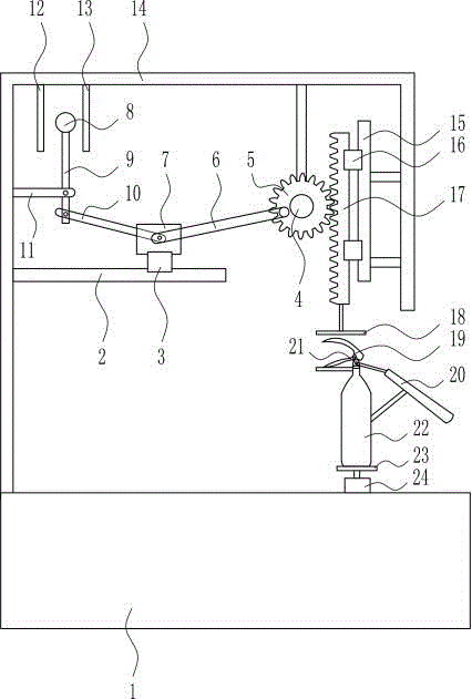
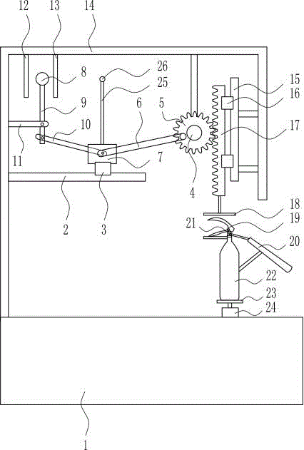
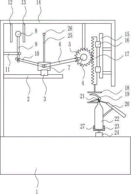
[0027] A transformer fire extinguishing warning device for electric power, such as Figure 1-3 As shown, it includes a first slide rail 2, a first slider 3, a first motor 4, a gear 5, a first swing lever 6, a connecting block 7, a knock block 8, a second swing lever 9, and a third swing lever 10 , fixed rod 11, first gong 12, second gong 13, bracket 14, second slide rail 15, second slider 16, rack 17, pressure plate 18, pressure handle 19, horn 20, safety pin 21 , carbon dioxide fire extinguisher 22, placement plate 23 and rotary motor 24, transformer 1 top is provided with support 14 and rotary motor 24, and rotary motor 24 top is provided with placement plate 23, and placement plate 23 is provided with carbon dioxide fire extinguisher 22, and carbon dioxide fire extinguisher 22 is provided with There are pressure handle 19, safety pin 21 and horn 20, and the top of bracket 14 is provided with the first gong 12, the second gong 13 and the first motor 4 in order from left to r...
PUM
Abstract
The invention relates to a fire extinguishment warning device, in particular to a fire extinguishment warning device for a power transformer and aims at solving the technical problems to provide the fire extinguishment warning device for the power transformer with timely fire extinguishment, large warning strength and safety in operation. The fire extinguishment warning device for the power transformer comprises a first sliding rail, a first sliding block, a first motor, a gear, a first oscillating rod, a connecting block, a knocking block, a second oscillating rod, a third oscillating rod, a fixing rod, a first gong, a second gong, a bracket, a second sliding rail, second sliding blocks, a rack, a pressure plate, a pressure handle, a horn, a safety pin, a carbon dioxide extinguisher, a placing plate and a rotary motor; the bracket and the rotary motor are arranged on the top of the transformer; the placing plate is arranged on the top of the rotary motor; and the carbon dioxide extinguisher is arranged on the placing plate and is provided with the pressure handle, the safety pin and the placing plate. The fire extinguishment warning device for the power transformer has the effects of timely fire extinguishment, large warning strength and safety in operation.
Description
technical field [0001] The invention relates to a fire extinguishing warning device, in particular to a fire extinguishing warning device for a power transformer. Background technique [0002] Electricity is an energy source powered by electrical energy. Invented in the 1870s, the invention and application of electricity set off the second industrialization climax. It has become one of the three scientific and technological revolutions in the world since the 18th century in human history. Since then, technology has changed people's lives. The large-scale power system that appeared in the 20th century is one of the most important achievements in the history of human engineering science. It is a power production and consumption system composed of power generation, power transmission, power transformation, power distribution and power consumption. It converts the primary energy of nature into electricity through mechanical energy devices, and then supplies electricity to vari...
Claims
Application Information
Patent Timeline
Application Date:The date an application was filed.
Publication Date:The date a patent or application was officially published.
First Publication Date:The earliest publication date of a patent with the same application number.
Issue Date:Publication date of the patent grant document.
PCT Entry Date:The Entry date of PCT National Phase.
Estimated Expiry Date:The statutory expiry date of a patent right according to the Patent Law, and it is the longest term of protection that the patent right can achieve without the termination of the patent right due to other reasons(Term extension factor has been taken into account ).
Invalid Date:Actual expiry date is based on effective date or publication date of legal transaction data of invalid patent.
Patent Type & Authority Applications(China)
IPC IPC(8): A62C3/16A62C35/00
CPCA62C3/16A62C35/00
Inventor 童妍
Owner SHENZHEN CITY FUTIAN DISTRICT SCI & TECH EDUCATION ASSOC FOR JUVENILES