

Reinforced rotation handle
A technology of rotating handles and handles, applied in the directions of hand-held tools, instruments, control components, etc., can solve the problems of increased size matching gap, front and back shaking, etc., and achieve the effect of increasing the degree of stability, the rotation process is firm, and the structure principle is simple and clear.
- Summary
- Abstract
- Description
- Claims
- Application Information
AI Technical Summary
Problems solved by technology
Method used
Image

Examples
Embodiment Construction
[0010] The present invention will be further illustrated below in conjunction with the accompanying drawings and specific embodiments. This embodiment is implemented on the premise of the technical solution of the present invention. It should be understood that these embodiments are only used to illustrate the present invention and are not intended to limit the scope of the present invention.
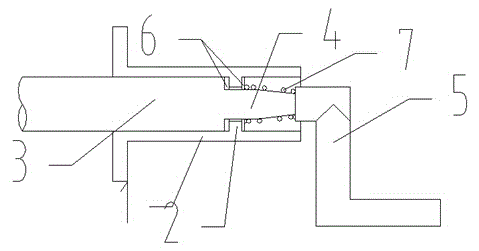
[0011] Such as figure 1 As shown, a reinforced rotary handle 5 includes a rotary branch pipe 1 , a stop ring 2 , a rotary spindle 3 , a connecting rod 4 , a handle 5 , a gasket 6 , and a spring 7 .
[0012] The limit stop ring 2 is located in the middle of the inner ring surface of the rotating branch pipe 1, and the center of the right end face of the rotating main shaft 3 is fixedly connected with one end of the connecting rod 4.
[0013] The other end of connecting rod 4 is fixedly connected with the end face of the rotation center cylinder of handle 5, and connecting rod 4 is posit...
PUM
 Abstract
Description
Claims
Application Information