An electric vehicle battery thermal management system

A battery thermal management, electric vehicle technology, applied in secondary batteries, circuits, electrical components, etc., can solve problems such as poor heat dissipation, and achieve the effect of improving heat exchange rate, small resistance loss, and reducing energy consumption

Active Publication Date: 2020-03-24
CHERY AUTOMOBILE CO LTD
View PDF1 Cites 0 Cited by
  • Summary
  • Abstract
  • Description
  • Claims
  • Application Information

AI Technical Summary

Problems solved by technology

[0006] In order to solve the problem of poor heat dissipation in the prior art, an embodiment of the present invention provides a thermal management system for an electric vehicle battery

Method used


Image

  • An electric vehicle battery thermal management system
  • An electric vehicle battery thermal management system
  • An electric vehicle battery thermal management system

Examples


Embodiment 1

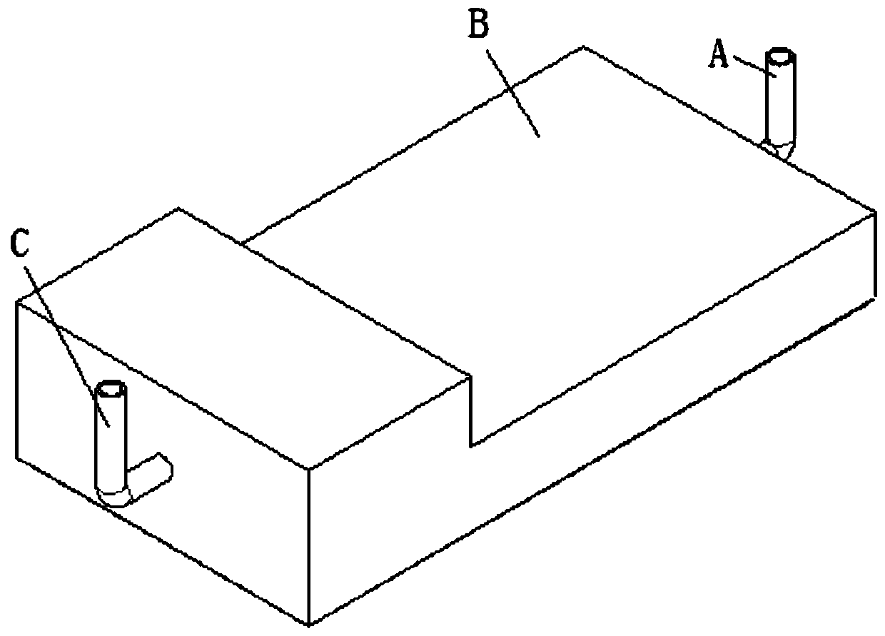
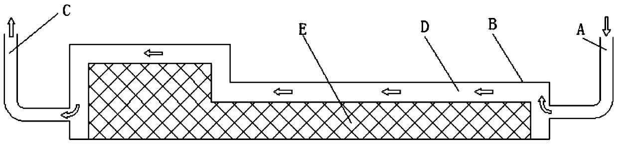
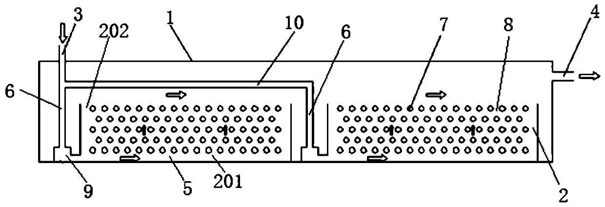
[0044] An embodiment of the present invention provides an electric vehicle battery thermal management system, such as image 3 As shown, the electric vehicle battery thermal management system includes: a battery pack case 1; a plurality of battery modules 2 connected at the bottom of the battery pack case 1; 3, and the battery pack air outlet 4 provided at the other end of the upper part of the battery pack case 1;

[0045] Wherein, the bottom 201 of the battery module is provided with a cavity 5;

[0046] There is a heat dissipation air duct 6 inside the battery pack housing 1, and the upper end of the heat dissipation air duct 6 is connected to the air inlet 3 of the battery pack, and the lower end of the heat dissipation air duct 6 communicates with the cavity 5;

[0047] There are gaps 8 between the cells 7 inside the battery module 2 .

[0048] When the electric car is discharged, the battery cell 7 continuously generates heat, and the battery temperature continues to r...

Embodiment 2

[0055] An embodiment of the present invention provides an electric vehicle battery thermal management system, such as Figure 4 As shown, the electric vehicle battery thermal management system includes: a battery pack housing 1; a plurality of battery modules 2 connected to the top of the battery pack housing 1; a battery pack air inlet provided at one end of the lower part of the battery pack housing 1 3, and the battery pack air outlet 4 provided at the other end of the lower part of the battery pack case 1;

[0056] Wherein, the bottom 201 of the battery module is provided with a cavity 5;

[0057] There is a heat dissipation air duct 6 inside the battery pack housing 1, and the lower end of the heat dissipation air duct 6 is connected to the air inlet 3 of the battery pack, and the upper end of the heat dissipation air duct 6 communicates with the cavity 5;

[0058] There are gaps 8 between the cells 7 inside the battery module 2 .

[0059] When the electric car is disch...


PUM


Abstract

The invention discloses a heat management system for an electric vehicle battery, which belongs to the field of electric vehicle batteries. The system includes: a battery pack housing; a plurality of battery modules connected at the bottom of the battery pack housing; a battery pack air inlet provided at one end of the upper part of the battery pack housing; The battery pack air outlet provided at the other end; wherein, the bottom of the battery module is provided with a cavity; there is a cooling air duct inside the battery pack housing, and the upper end of the cooling air duct is connected to the battery pack air inlet, and the lower end of the cooling air duct is It communicates with the cavity; there are gaps between the cells inside the battery module. In the present invention, the upper end of the heat dissipation air duct is connected to the air inlet of the battery pack, and the lower end is connected to the cavity at the bottom of the battery module, so that the air enters from the bottom of the battery module, passes through the gap between the battery cells, and then flows from the battery module. The upper part is blown out, thereby improving the heat exchange rate between the air and the battery cell.

Description

technical field [0001] The invention relates to the field of electric vehicle batteries, in particular to a heat management system for electric vehicle batteries. Background technique [0002] With the development of social economy and the increase of energy demand, the voice of new energy technology is getting higher and higher, and the development of electric vehicles has become the general trend. As the core part of electric vehicles, battery performance and service life directly determine the performance and cost of electric vehicles. When the battery used in electric vehicles is being charged and discharged, the temperature inside the battery cell is getting higher and higher, even exceeding the safe use range, resulting in thermal runaway. In order to ensure the efficient and reliable operation of the battery, it is very important to design a reasonable electric vehicle battery thermal management system. [0003] At present, the electric vehicle battery thermal manag...

Claims


Application Information

Patent Timeline
Patent Type & Authority Patents(China)
IPC IPC(8): H01M10/613H01M10/617H01M10/625H01M10/6557H01M10/6566
CPCH01M10/613H01M10/617H01M10/625H01M10/6557H01M10/6566Y02E60/10
Inventor 倪绍勇曾祥兵陶玉鹏
Owner CHERY AUTOMOBILE CO LTD
Why Eureka
Try Eureka