Teaching demonstration instrument capable of being made by oneself
What is Al technical title?
Al technical title is built by PatSnap Al team. It summarizes the technical point description of the patent document.
A demonstrator and indicating technology, which is applied in the direction of teaching models, instruments, educational tools, etc., can solve the problems that students cannot make by themselves, teaching instruments cannot be popularized, and the types of experimental instruments are insufficient. , a wide variety of effects
Inactive Publication Date: 2017-05-24
CHONGQING ZUNLAI TECH
View PDF6 Cites 1 Cited by
Summary
Abstract
Description
Claims
Application Information
AI Technical Summary
This helps you quickly interpret patents by identifying the three key elements:
Problems solved by technology
Method used
Benefits of technology
Problems solved by technology
Therefore, the various experimental instruments in teaching are constantly improving, but there are still many shortcomings: First, the types of experimental instruments are insufficient, especially the experimental instruments for low-grade students are not comprehensive
Second, the spirit of entertaining and teaching in teaching instruments is not enough. Third, the cost of most teaching instruments is too high. Therefore, for some remote village schools, many common teaching instruments cannot be popularized.
Fourth, the instruments are too complicated for students to make by themselves, so they cannot cultivate their good habits of doing things and their enthusiasm for science by letting them make their own instruments
Method used
Image
Click on the blue label to locate the original text in one second.
Reading with bidirectional positioning of images and text.
Examples
Embodiment Construction
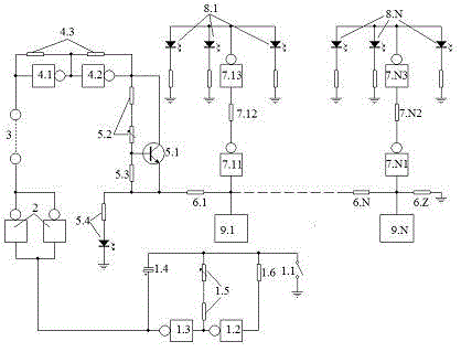
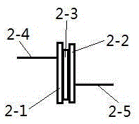
[0067] figure 1 , figure 2 It is a way of concrete implementation.
[0068] 1. Options: The two gates in the oscillation stage, the two gate circuits in the power amplifier stage, the two gates in the amplifier stage, and the inverter in the display start-up unit all use integrated circuit CD4069. The balanced transistor is an NPN transistor. The balanced upper bias resistor is composed of an adjustable resistor connected in series with a fixed resistor.
[0069] 2. Welding: The specific electronic components of each part are connected as follows: figure 1 Soldering, self-made capacitors such as figure 2 Welding as shown: Use two copper sheets to weld one lead wire respectively, then paste the two copper sheets together with double-sided tape, and insert the two lead wires into the test hole respectively.
[0070] Three, debugging.
[0071] Insert a self-made capacitor into the test hole. When the transfer switch is on, it is regarded as direct current, and when the t...
PUM
Abstract
The invention discloses a teaching demonstration instrument capable of being made by oneself, which belongs to the field of teaching instrument demonstration. The teaching demonstration instrument is composed of a self-made capacitor, a change-over switch, a test hole, an oscillator stage, a power amplifier stage, an amplification stage, an equilibrium stage, a voltage division stage, display stages and voice stages. The teaching demonstration instrument aims at allowing students to make objects such as instruments, inductors, capacitors resistors by themselves, and cultivating operational ability of the students. When the self-made capacitor is inserted into the test hole and the change-over switch is in a switching-on state, namely, in a direct current state, the display stages only flash once; when in an alternating current state, namely, the change-over switch is in a switching-off state, the oscillator stage oscillates, high-low conversion of power amplifier stage output occurs, the self-made capacitor forms a charging-discharging state, the equilibrium stage is broken down through amplification by means of the amplification stage, the voltage division stage is started, the display stages and the voice stages form light and sound display, and when oscillation frequency is accelerated, the more display states and the voice stages are started, thus the conductive performance of the object is displayed from another aspect, and the teaching demonstration instrument can be an instrument popularized in schools.
Description
technical field [0001] The utility model belongs to the field of teaching instrument demonstration. Background technique [0002] Innovation is the soul of a nation, and young students are the power of innovation. [0003] The strength of a country lies in its talents, and the cultivation of talents lies in education. The focus of education on young people is that the country is strong when young people are strong, and the country progresses when young people progress. To cultivate young people's love for science, improving the quality of teaching is the key, and the accuracy of experimental instruments is an important factor in improving teaching. The experiments are more convincing, so that students can understand things, understand natural phenomena, inspire students' thinking, and play an important role in improving the level of education. Therefore, various experimental instruments in teaching are constantly improving, but there are still many deficiencies: First, the...
Claims
Application Information
Patent Timeline
Application Date:The date an application was filed.
Publication Date:The date a patent or application was officially published.
First Publication Date:The earliest publication date of a patent with the same application number.
Issue Date:Publication date of the patent grant document.
PCT Entry Date:The Entry date of PCT National Phase.
Estimated Expiry Date:The statutory expiry date of a patent right according to the Patent Law, and it is the longest term of protection that the patent right can achieve without the termination of the patent right due to other reasons(Term extension factor has been taken into account ).
Invalid Date:Actual expiry date is based on effective date or publication date of legal transaction data of invalid patent.