Check patentability & draft patents in minutes with Patsnap Eureka AI!

A special punching device for installation of building decorative panels

A punching device and architectural decoration technology, which is applied in metal processing and other directions, can solve the problems of poor punching accuracy, waste of decorative panels, hidden safety hazards, etc., and achieve the effects of convenient operation, improved work efficiency, and improved safety

Inactive Publication Date: 2018-01-19
斯特龙城市更新股份有限公司
View PDF5 Cites 0 Cited by
  • Summary
  • Abstract
  • Description
  • Claims
  • Application Information

AI Technical Summary

Problems solved by technology

[0002] Architectural decorative panels directly reflect the decorative effect of buildings, use natural or artificial materials to express the designer's decorative design style, and play a better role in covering and protecting the wall. During processing, it is necessary to perform drilling operations in advance to make the decorative panels Easy to install, building decorative panels often need to be punched during installation and use, and then the factory uses a punching device to perform drilling operations when processing building decorative panels, which is convenient for direct installation in the later stage and improves construction efficiency. Traditional punching devices are easy to cause Offset, waste of decorative panels, and there are great safety hazards, low efficiency, poor drilling accuracy, not suitable for existing needs

Method used


Image

  • A special punching device for installation of building decorative panels
  • A special punching device for installation of building decorative panels
  • A special punching device for installation of building decorative panels

Examples


Embodiment Construction

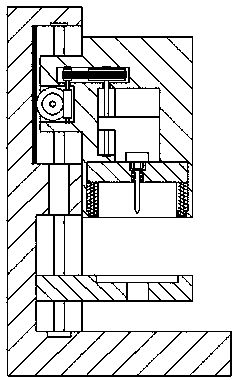
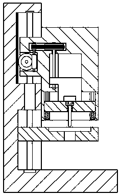
[0023] Such as Figure 1-Figure 5 As shown, a special punching device for the installation of building decorative boards according to the present invention includes a body 6 composed of a support column 62 and a base 61, and an upper chute 622 and a lower chute 621 are provided in the right end surface of the support column 62. The inner wall on the left side of the upper chute 622 is provided with a rack 6222 extending up and down, the upper threaded rod 6221 is provided in the upper chute 622, and the upper threaded rod 6221 is provided in the chute 621. The lower threaded rod 6211, the right side of the upper chute 622 is provided with a perforating and driving device 8, and the left side end surface of the perforating and driving device 8 is provided with a screw that extends into the upper chute 622 and is connected with the upper screw thread. The rod 6221 is threadedly matched with the connected slide block 81. A groove 87 is provided in the left end surface of the slid...


PUM


Abstract

The invention discloses a special perforating device for mounting a building decoration board. The special perforating device comprises a machine body consisting of a support pillar and a base, wherein an upper chute and a lower chute are formed in the end surface of the right side of the support pillar; a rack arranged in an up-and-down stretching manner is arranged on the inner wall of the left side of the upper chute; an upper threaded rod arranged in an up-and-down stretching manner is arranged in the upper chute; a lower threaded rod arranged in an up-and-down stretching manner is arranged in the lower chute; a perforating driving and guiding device is arranged on the right side of the upper chute; a slider extending into the upper chute and being in threaded matched connection with the upper threaded rod is arranged on the end surface of the left side of the perforating driving and guiding device; a groove is formed in the end surface of the left side of the slider; a lifting chute is arranged in the position, on the right side of the groove, in the perforating driving and guiding device; a sliding and embedding cavity is arranged at and communicates with the bottom of the lifting chute; a first chute is formed in the inner wall of the left side of the lifting chute; and a transmission cavity is arranged between the wall, at the upper part of the right side of the groove, of the slider and the wall, at the upper part of the left side of the lifting chute, of the perforating driving and guiding device. The special perforating device for mounting the building decoration board is simple in structure and convenient to operate, the equipment and personnel security during perforating operation is improved, and the working efficiency is improved.

Description

technical field [0001] The invention relates to the technical field of building engineering construction equipment, in particular to a special punching device for installing building decorative panels. Background technique [0002] Architectural decorative panels directly reflect the decorative effect of buildings, use natural or artificial materials to express the designer's decorative design style, and play a better role in covering and protecting the wall. During processing, it is necessary to perform drilling operations in advance to make the decorative panels Easy to install, building decorative panels often need to be punched during installation and use, and then the factory uses a punching device to perform drilling operations when processing building decorative panels, which is convenient for direct installation in the later stage and improves construction efficiency. Traditional punching devices are easy to cause Offset, waste of decorative panels, and there is a gr...

Claims


Application Information

Patent Timeline
Patent Type & Authority Patents(China)
IPC IPC(8): B26F1/16B26D5/08B26D7/00
CPCB26D5/083B26D7/0006B26F1/16
Inventor 贾轩范玉玲陆旺贾士清赵丽鹏宋志华张博超曹雪丽
Owner 斯特龙城市更新股份有限公司
Features
  • R&D
  • Intellectual Property
  • Life Sciences
  • Materials
  • Tech Scout
  • Unparalleled Data Quality
  • Higher Quality Content
  • 60% Fewer Hallucinations
Learn More