Experimental device for simulating impact of upstream dam break on downstream dam

An experimental device and upstream technology, applied in the direction of hydraulic models, etc., can solve the problems of downstream dam impact and less damage, and achieve the effects of strong operability, saving experimental time, and simple production principles

Active Publication Date: 2017-08-15
SICHUAN UNIV +1
View PDF5 Cites 2 Cited by
  • Summary
  • Abstract
  • Description
  • Claims
  • Application Information

AI Technical Summary

Problems solved by technology

In the cascade dam group, the impact and damage of the upstream dam failure flood on the downstream dam, and the quantitative analysis of the impact of the upstream reservoir dam failure with different storage capacity on the downstream dam are few, and in-depth research is urgently needed.

Method used


Image

  • Experimental device for simulating impact of upstream dam break on downstream dam
  • Experimental device for simulating impact of upstream dam break on downstream dam
  • Experimental device for simulating impact of upstream dam break on downstream dam

Examples


Embodiment 1

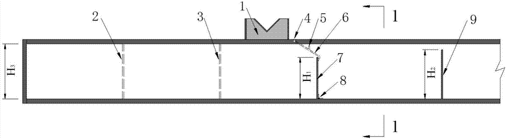
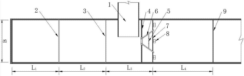
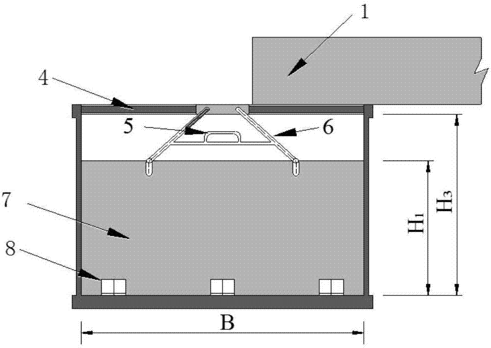
[0033] The structure of the cascade dam break experiment device is as follows: figure 1 with figure 2 As shown, it includes a triangular weir water delivery system, a water tank, a partition, an upstream arch dam model baffle 7 and a downstream arch dam model baffle 9 . The width B of the tank is 80cm; the height of the baffle plate 7 of the upstream arch dam model is H 1 30cm, the downstream arch dam model baffle 9 height H 2 is 40cm, the sink height H 350cm; storage capacity length L 1 is 80cm, the distance L between the first-stage partition groove and the second-stage partition groove 2 is 80cm, the distance L between the second-stage diaphragm groove and the baffle plate 7 of the upstream arch dam model 3 is 80cm, the distance L between the upstream arch dam model baffle 7 and the downstream arch dam model baffle 9 4 It is 160cm.

[0034] In this case, with different partitions inserted, the storage capacity of the upstream reservoir can be 0.192m 3 、0.384m 3 、0...

Embodiment 2

[0036] The width B of the tank is 100cm; the height of the baffle plate 7 of the upstream arch dam model is H 1 is 50cm, the downstream arch dam model baffle 9 height H 2 is 70cm, the sink height H 3 80cm; storage capacity length L 1 is 120cm, the distance L between the first-stage partition groove and the second-stage partition groove 2 is 100cm, the distance L between the second-stage diaphragm groove and the baffle plate 7 of the upstream arch dam model 3 is 80cm, the distance L between the upstream arch dam model baffle 7 and the downstream arch dam model baffle 9 4 It is 230cm.

[0037] In this case, with different partitions inserted, the storage capacity of the upstream reservoir can be 0.40m 3 、0.90m 3 、1.50m 3 . Under different upstream reservoir capacity conditions, the impact damage characteristics of the upstream arch dam failure to the downstream arch dam (non-breakage) were quantitatively analyzed.

[0038] To sum up, in traditional dam failure experimen...


PUM


Abstract

The invention discloses an experimental device for simulating the impact of the upstream dam break on a downstream dam. The experimental device comprises a water tank, an upstream arch dam model baffle and a downstream arch dam model baffle. The upstream arch dam model baffle and the downstream arch dam model baffle are arranged in the water tank. At least two levels of storage capacities are set in the water tank on the upstream position of the upstream arch dam model baffle. The adjacent two levels of storage capacities are partitioned by partitions which can adjust the capacity of the storage capacities. A water injection device for injecting water into the water tank is arranged above the water tank. A monitoring instrument for obtaining the flood routing characteristic of the upstream arch dam model baffle and the characteristics of the impact and destroy of the flood on the downstream position is arranged on the downstream arch dam mold baffle. The experimental device is simple in structure, the experimental scheme is convenient to adjust and optimize, the operability and practicability are high, and the experimental device can be widely applied to dam break and cascade dam break model experiments.

Description

technical field [0001] The invention relates to the technical field of hydraulic model experiment facilities, in particular to a facility for simulating the upstream arch dam failure in the study of cascade dam failure, but the downstream dam does not fail, and the upstream dam failure flood causes impact damage to the downstream dam Experimental sink setup. Background technique [0002] Simulation experiments on dam failures are often carried out in water tanks. According to the form of dam failure, dam failures can be divided into three categories: instantaneous total collapse, instantaneous partial collapse, and gradual collapse. Once an arch dam breaks, it usually collapses instantaneously. If the flood collapses instantly, the flood is often accompanied by large peak flow, severe flow process, strong destructive power, and huge disasters. At present, many rivers in our country have successively carried out cascade development. While achieving greater comprehensive be...

Claims


Application Information

Patent Timeline
Patent Type & Authority Applications(China)
IPC IPC(8): E02B1/02
CPCE02B1/02
Inventor 牛志攀张超然於三大苏立文小浩马旭东
Owner SICHUAN UNIV
Why Eureka
Try Eureka