
Intelligent sewage draining controller for closestools
A controller and intelligent technology, which is applied in the field of intelligent sewage controller and sewage controller, can solve the problems of high cost of intelligent toilet seat, embarrassing sound of sewage discharge, poor sanitation and other problems, so as to broaden the scope of use, solve sanitary problems, and have a reasonable structure Effect
- Summary
- Abstract
- Description
- Claims
- Application Information
AI Technical Summary
Problems solved by technology
Method used
Image

Examples
Embodiment Construction
[0015] The present invention will be further described below in conjunction with accompanying drawing:
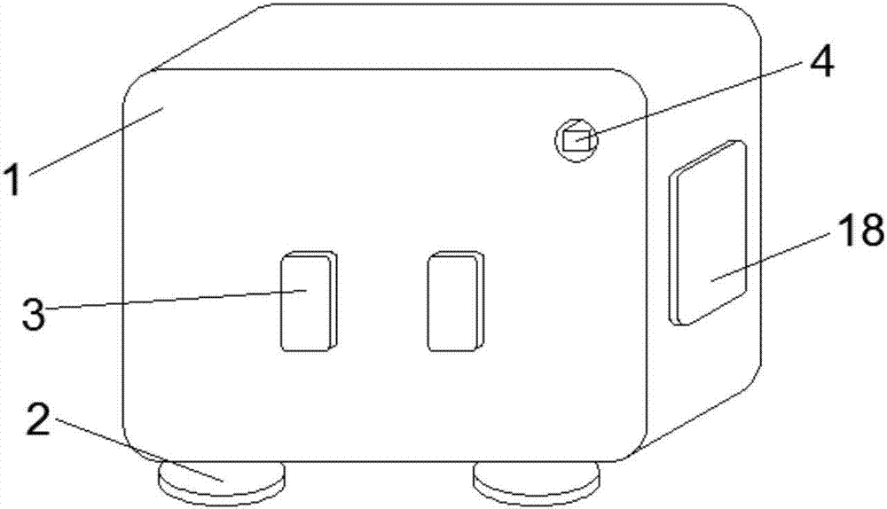
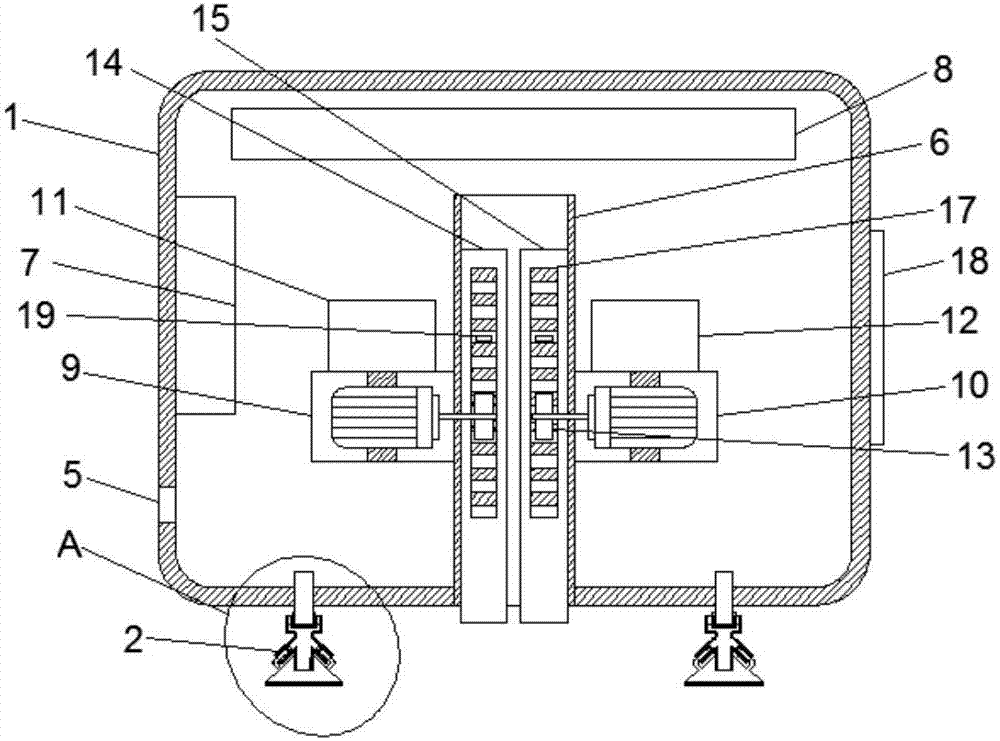
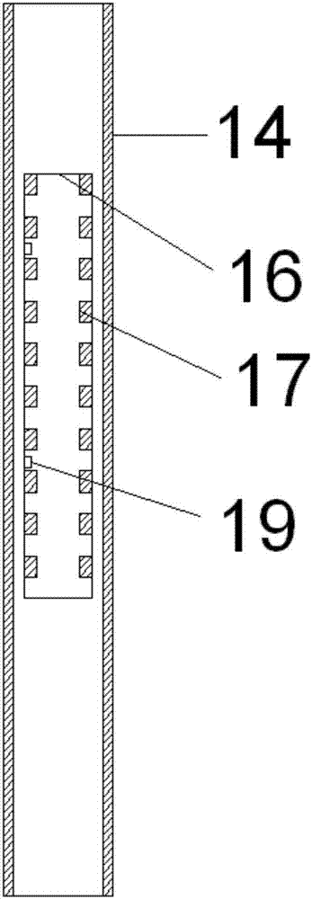
[0016] Such as Figure 1-5 As shown, an intelligent sewage controller includes a housing 1, two adsorption devices 2 are fixedly installed at the bottom of the housing 1, the adsorption device 2 includes a fixed shaft 21, and the bottom end of the fixed shaft 21 is sleeved with a rotating bearing 22, and The outer side of the rotating bearing 22 is sleeved with the first rubber pad 23, the first rubber pad 23 can rotate through the rotating bearing 22, the top of the first rubber pad 23 is welded with a limit block 24, and the limit block 24 connects the first rubber pad The position of 23 is limited, and the bottom end of the first rubber pad 23 is closely attached to the second rubber pad 25. Due to the fixing of the limit block 24, the first rubber pad 23 and the second rubber pad 25 can be closely attached. The left and right sides of a rubber pad 23 and the second rub...
PUM
 Abstract
Description
Claims
Application Information