
Adjustable supporting seat for surveillance camera
A monitoring camera and adjusting plate technology, which is applied to supporting machines, machines/brackets, CCTV systems, etc., can solve the problem that the camera cannot be adjusted in angle, and achieve the effect of increasing the monitoring range, improving the range, and avoiding damage.
- Summary
- Abstract
- Description
- Claims
- Application Information
AI Technical Summary
Problems solved by technology
Method used
Image

Examples
Embodiment Construction
[0012] The present invention will be further described below in conjunction with the accompanying drawings.
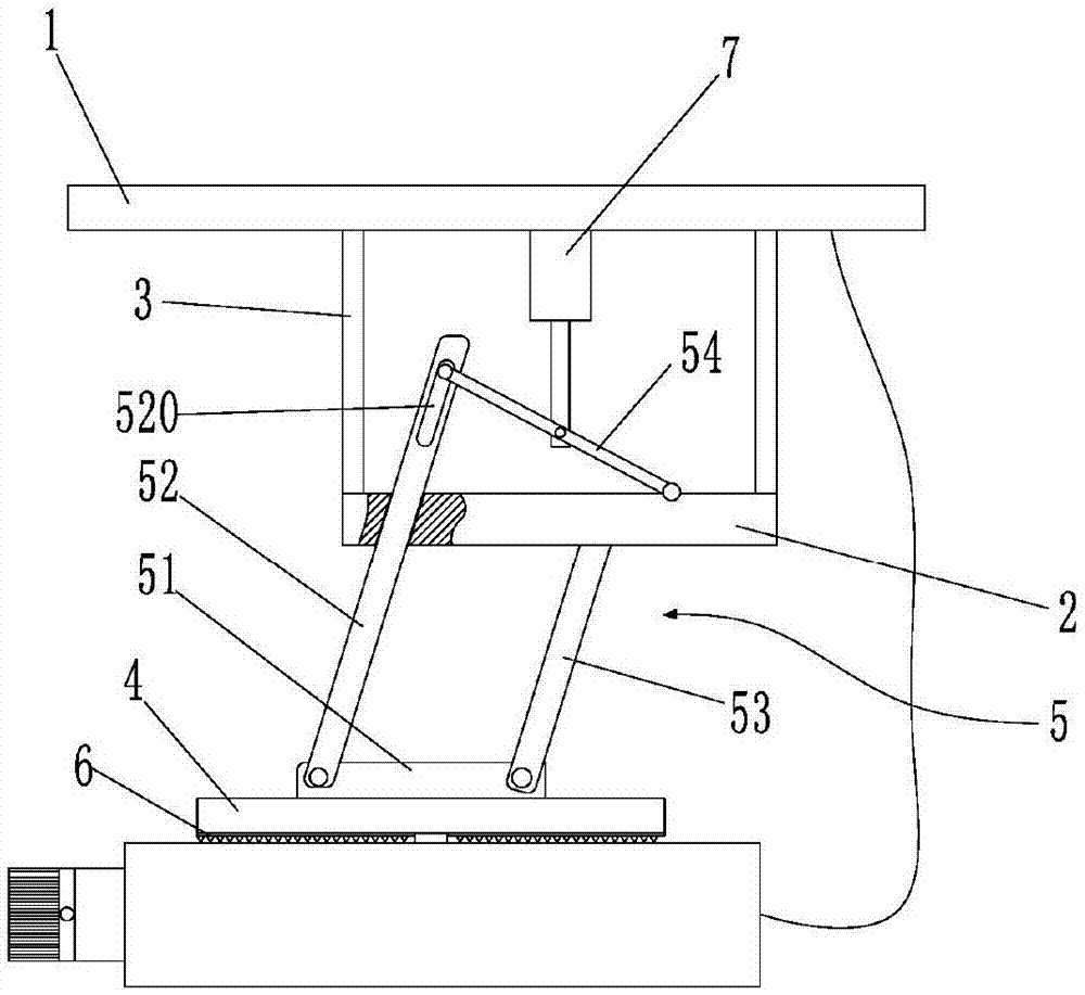
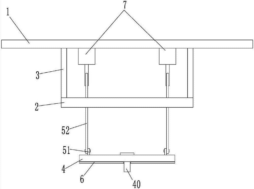
[0013] like Figure 1 ~ Figure 2 As shown, an adjustable support for a monitoring camera according to the present invention includes parallel mounting plates 1 and connecting plates 2, and a plurality of support rods 3 are connected between the mounting plates 1 and connecting plates 2, Thereby forming the fixed part of the whole adjustable support, it will carry the weight of all parts installed on the adjustable support, and the support rods 3 are four, and are evenly distributed on the edge of the connecting plate 2, so that each support The rod 3 is evenly stressed, can support the components installed below the connecting plate 2, and can also prevent the connecting plate 2 from moving relative to each other, making it inconvenient to maintain the distance between the connecting plate 2 and the mounting plate 1. Four mounting holes located on the same circumferen...
PUM
 Abstract
Description
Claims
Application Information