Al technical title is built by PatSnap Al team. It summarizes the technical point description of the patent document.
A vacuum device and energy-saving technology, applied in the field of vacuum pumping, can solve the problems of cavitation, large power consumption of equipment operation, large maintenance workload, etc., and achieve the effect of suppressing pressure fluctuation, reducing coal consumption for power generation, and reliable and safe operation.
Active Publication Date: 2018-01-09
WUHAN EDW PUMP & VALVE
View PDF6 Cites 2 Cited by
Summary
Abstract
Description
Claims
Application Information
AI Technical Summary
This helps you quickly interpret patents by identifying the three key elements:
Problems solved by technology
Method used
Benefits of technology
Problems solved by technology
Under vacuum conditions, a large amount of working fluid of the water ring vacuum pump vaporizes to cause cavitation, and then problems such as vibration and noise occur. The suction characteristics of the water ring vacuum pump are greatly reduced, and the dry air in the condenser cannot be pumped out in time. Affect the vacuum of the condenser, seriously affecting the safe and stable operation of the unit and the economy of operation;
[0004] 2. In the traditional vacuum system of the unit, the water ring vacuum pump is configured according to the requirements of the unit to establish a vacuum. The operation of the equipment consumes a lot of power. Under the condition of maintaining the vacuum of the unit, there is a lot of room for consumption reduction;
[0006] 4. The water ring vacuum pump is a rotating device, the wear of the impeller and the occurrence of cavitation phenomenon, the workload of daily maintenance is very large
Method used
Image
Click on the blue label to locate the original text in one second.
Reading with bidirectional positioning of images and text.
Examples
Embodiment Construction
[0025] In order to make the object, technical solution and advantages of the present invention clearer, the present invention will be further described in detail below in conjunction with the accompanying drawings and embodiments. It should be understood that the specific embodiments described here are only used to explain the present invention, not to limit the present invention.
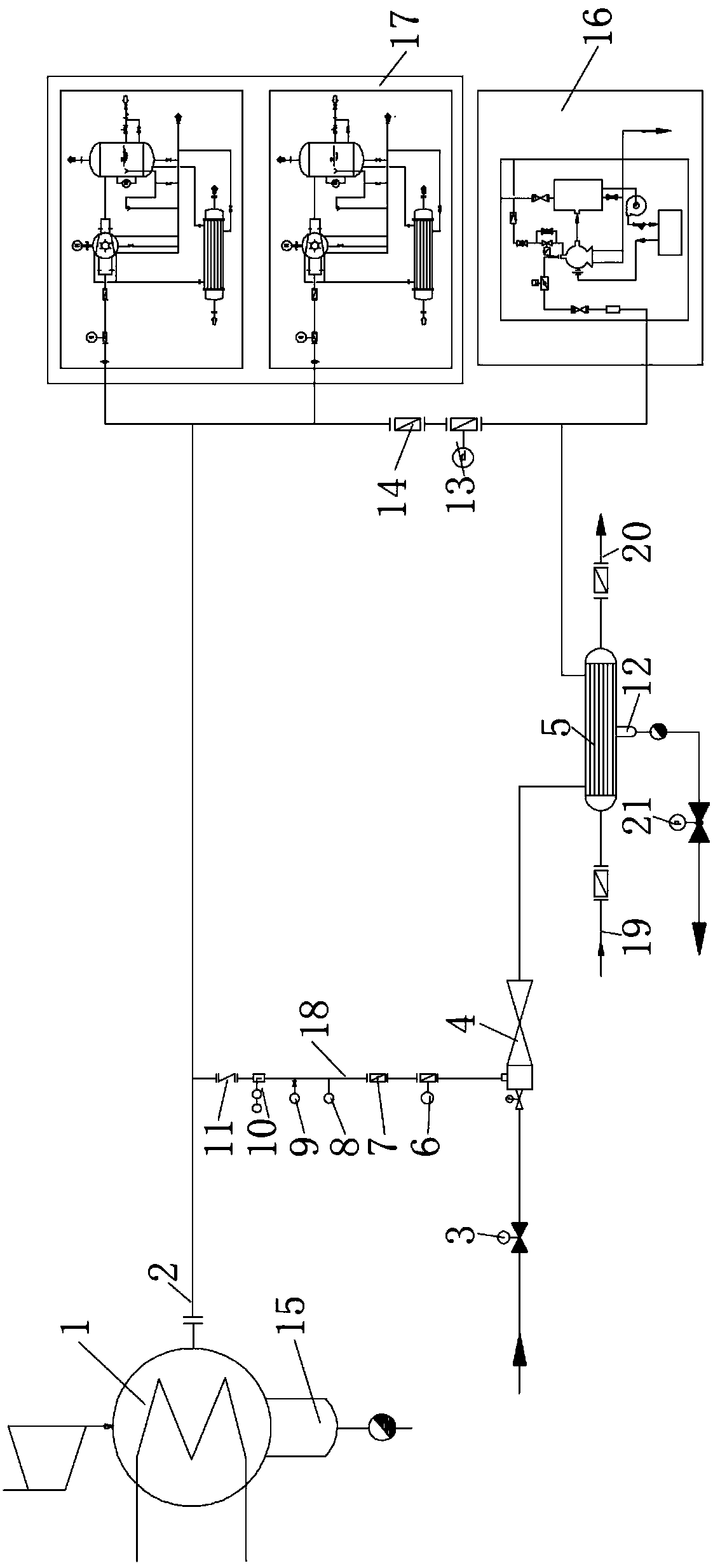
[0026] see figure 1 , an energy-saving vacuum device, including a condenser 1, a condenser hot well 15, a condensing main pipe 2 and a first water ring vacuum pump system 17, and also includes a condensing branch pipe 18, a condensing pipeline check valve 11, Condensate pipeline flowmeter 10, condensate pipeline pressure transmitter 9, condensate pipeline thermal resistance 8, condensate pipeline isolation valve 7, condensate pipeline pneumatic valve 6, power steam regulating valve 3, steam injector 4, pipe type Heat exchanger 5, steam trap 12, steam trap pneumatic valve 21, communication pneumati...
PUM
Abstract
The invention relates to an energy-saving type vacuum device. The energy-saving type vacuum device comprises a condenser, a condenser hot well, a steam condensing mother pipe, a first water ring vacuum pump system, a steam condensing branch pipe, a steam condensing pipeline check valve, a steam condensing pipeline flow meter, a steam condensing pipeline pressure transmitter, a steam condensing pipeline thermal resistor, a steam condensing pipeline isolating valve, a steam condensing pipeline pneumatic valve, a power steam adjusting valve, a steam ejector, a tubular heat exchanger, a steam trap, a hydrophobic pneumatic valve, a contact pneumatic valve, a contact isolation valve and a second water ring vacuum pump. According to the energy-saving type vacuum device, the first water ring vacuum pump system is replaced by the tubular heat exchanger and the small-power second water ring vacuum pump, thus the vacuum of the condenser can be maintained and provided, the condenser is guaranteedto be in the optimum working condition, the influence of environmental temperature changes is avoided, stable pumping capacity of the condenser is kept all the time, the vacuum degree of the condenseris improved, the power generation coal consumption of a unit is reduced, the operation power consumption of a vacuum pumping system is reduced, operation of the system equipment is reliable and safe,the maintenance workload is small, the cavitation phenomenon is avoided, and the phenomena of high noise and vibration are avoided.
Description
technical field [0001] The invention relates to the technical field of vacuuming, in particular to an energy-saving vacuum device and a control method thereof. Background technique [0002] Condenser is one of the important equipment of thermal power generating set, and the vacuum value of condenser has an important influence on the economy of turbo-generating set operation. There are many factors that affect the vacuum of the condenser, among which the most direct impact is vacuum tightness, cooling water temperature, cooling water volume, and the working characteristics of the water ring vacuum pump. At present, the condenser vacuum pumping system of domestic 300MW and above generator sets mostly adopts 2 or 3 water ring vacuum pump units, and the water ring vacuum pump has the following disadvantages: [0003] 1. The temperature of the working fluid of the water ring vacuum pump is greatly affected by the temperature of the cooling water, and the ambient temperature is a...
Claims
Application Information
Patent Timeline
Application Date:The date an application was filed.
Publication Date:The date a patent or application was officially published.
First Publication Date:The earliest publication date of a patent with the same application number.
Issue Date:Publication date of the patent grant document.
PCT Entry Date:The Entry date of PCT National Phase.
Estimated Expiry Date:The statutory expiry date of a patent right according to the Patent Law, and it is the longest term of protection that the patent right can achieve without the termination of the patent right due to other reasons(Term extension factor has been taken into account ).
Invalid Date:Actual expiry date is based on effective date or publication date of legal transaction data of invalid patent.