Photoelectric effect tester

A photoelectric effect and tester technology, which is applied in the direction of instruments, measuring device shells, and sound-generating instruments, can solve the problems of no protective shell, no heat dissipation plate, and no sound-absorbing board, etc., so as to increase the air circulation speed and structure. Scientific and reasonable, safe and convenient to use

Inactive Publication Date: 2018-01-09
FOSHAN SAIWEI PHOTOELECTRIC TECH CO LTD
View PDF8 Cites 6 Cited by
  • Summary
  • Abstract
  • Description
  • Claims
  • Application Information

AI Technical Summary

Problems solved by technology

[0004] The present invention provides a photoelectric effect tester, which can effectively solve the problems in the above-mentioned background technology that no protective case is provided, the pressure resistance of the tester body cannot be improved, no heat dissipation plate is provided, the air circulation speed cannot be increased, and the heat dissipation effect cannot be improved. , cannot improve the service life of the tester body, does not have a handle, cannot carry the tester body easily, does not set a USB charging port, cannot improve the battery life of the mobile device, does not set a sound-absorbing board, cannot absorb the noise generated by the tester body, There is no leveling screw and support feet, the level of the detector body cannot be adjusted, the first shock absorbing spring and the first buffer plate are not installed, and the detector body cannot be protected during the movement

Method used


Image

  • Photoelectric effect tester
  • Photoelectric effect tester
  • Photoelectric effect tester

Examples


Embodiment

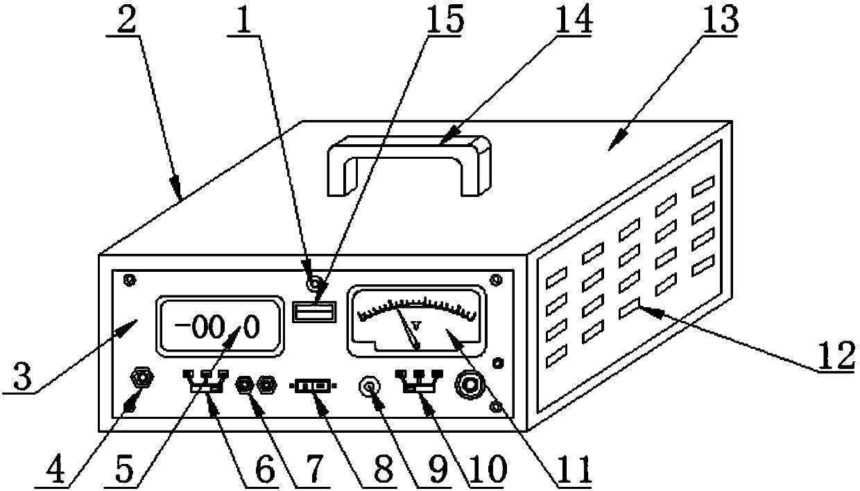
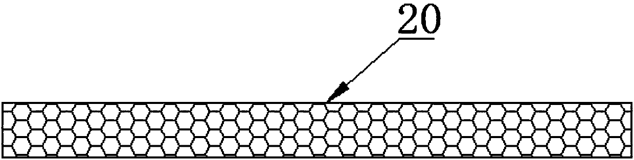
[0024] Example: such as Figure 1-5 As shown, the present invention provides a technical solution, a photoelectric effect tester, including a charging indicator light 1, a protective case 2, a tester body 3, a voltage input interface 4, a test display screen 5, a current control button 6, a voltage output Interface 7, switch 8, voltage polarity knob 9, voltage control button 10, voltage display meter 11, cooling plate 12, upper cover plate 13, handle 14, USB charging interface 15, belt 16, motor 17, driven pulley 18, Fixed rod 19, sound-absorbing plate 20, fixed seat 21, fan blade 22, driving pulley 23, support foot 24, leveling screw rod 25, first damping spring 26, air inlet plate 27, first buffer plate 28, second damper Shock spring 29 and the second buffer plate 30, the outside of the tester body 3 is fixed with a protective case 2, and the front surface of the tester body 3 is embedded with a test display screen 5, which is close to the test display screen on the tester b...


PUM


Abstract

The invention discloses a photoelectric effect tester. The photoelectric effect tester includes a charging indication lamp, a tester body, a switch and a voltage polarity knob; a protective shell is fixed onto the exterior of the tester body; and a voltage input interface, which is adjacent to the bottom end of a test display screen, is embedded into the front surface of the tester body. Accordingto the photoelectric effect tester of the invention, the protective shell is adopted, so that the compressive capability of the tester body can be improved, and the detector body can be prevented from being damaged by external collision; a heat-dissipating plate is adopted, so that air circulation speed can be increased through the rotation of fan blades, and therefore, a heat dissipation effectcan be improved, and the service life of the tester body can be prolonged; and a first damping spring and a first buffer plate are adopted, so that the detector body can be protected during a movementprocess, and therefore, the problem of damage to the protective shell caused by hitting due to the swing of the detector body can be solved. The photoelectric effect tester of the invention has the advantages of convenient installation, convenience in carrying and suitability for general popularization and use. According to the photoelectric effect tester, the service life of the detector body can be prolonged.

Description

technical field [0001] The invention relates to the technical field of photoelectric effect testers, in particular to a photoelectric effect tester. Background technique [0002] Photoelectric detection technology is a new detection technology produced by the combination of optics and electronics. It mainly uses electronic technology to detect optical signals, and further transmits, stores, controls, calculates and displays. In principle, photoelectric detection technology can Detect all non-electricity that can affect the amount of light and light characteristics. It can convert the non-electricity information to be detected into optical information that is easy to accept through the optical system, and then use photodetectors to convert the optical information into electricity, and further amplify through the circuit. Processing, in order to achieve the purpose of electrical signal output. [0003] However, the photoelectric effect testers currently on the market have com...

Claims


Application Information

Patent Timeline
Patent Type & Authority Applications(China)
IPC IPC(8): G01D11/24F16F15/04H05K7/20G10K11/162
Inventor 傅飞艳
Owner FOSHAN SAIWEI PHOTOELECTRIC TECH CO LTD
Why Eureka
Try Eureka