Antenna built-in wireless transmitting and receiving device

A wireless transceiver equipment, built-in technology, applied in electrical components, transmission systems and other directions, can solve the problems of affecting the appearance, antenna occlusion, installation is not firm, etc., to achieve the effect of simple location, convenient installation and debugging

Inactive Publication Date: 2018-02-09
CHENGDU RUIYI INFORMATION TECH
View PDF0 Cites 0 Cited by
  • Summary
  • Abstract
  • Description
  • Claims
  • Application Information

AI Technical Summary

Problems solved by technology

In order to realize the data transmission and reception of two wireless transceiver devices, the wireless transceiver device must be within the antenna coverage of the paired wireless transceiver device, and in order to achieve the required receiving strength, the antenna needs to be adjusted to a suitable position according to the signal strength Partially cover or not cover the antenna, and because the antenna is built-in, the position of the antenna cannot be seen. When adjusting, only the entire wireless transceiver module can be adjusted as a whole.
In some occasions, such as elevator shaft accessories, the wireless transceiver module can only be hung according to a certain position, which is not securely installed and affects the appearance, and the suspension is likely to cause the position of the wireless transceiver module to change, thereby blocking the antenna or removing the initial blocking. Causes changes in signal reception strength
In addition, during the installation process, it is very inconvenient to carry out measurements and adjustments by hanging the installation

Method used


Image

  • Antenna built-in wireless transmitting and receiving device
  • Antenna built-in wireless transmitting and receiving device

Examples


Embodiment Construction

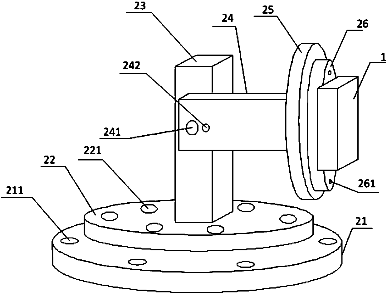
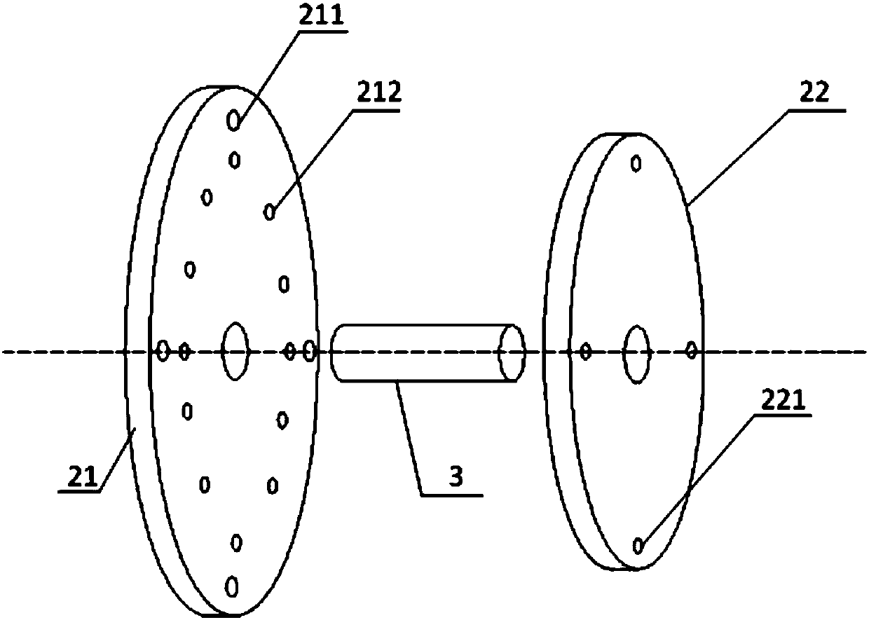
[0024] In order to make the purpose, technical solutions and advantages of the present invention clearer, the present invention will be further described in detail below in conjunction with the examples and accompanying drawings. As a limitation of the present invention.

[0025] In the following description, numerous specific details are set forth in order to provide a thorough understanding of the present invention. It will be apparent, however, to one of ordinary skill in the art that these specific details need not be employed to practice the present invention. In other instances, well-known structures, circuits, materials, or methods have not been described in detail in order to avoid obscuring the present invention.

[0026] Throughout this specification, reference to "one embodiment," "an embodiment," "an example," or "example" means that a particular feature, structure, or characteristic described in connection with the embodiment or example is included in the present...


PUM


Abstract

The invention discloses a wireless transceiver device with built-in antenna, which includes a wireless communication module and an installation base, the first rotating plate of the installation base can rotate in the plane where the first rotating plate is centered on the center of the circle; the first connecting rod The lower end is fixed at the center of the first rotating plate, and the upper end is rotationally connected to one end of the second connecting rod; one side of the second fixing plate is fixedly connected to the other end of the second connecting rod, and the other side is connected to one side of the second rotating plate, wirelessly The communication module is fixed on the other side of the second rotating plate, and the second rotating plate can rotate in the plane where the second rotating plate is centered on its center of circle. The present invention has an installation base through which the wireless communication module can be fixed on the wall or on the top, and after being fixed, the multi-directional rotation of the wireless communication module can be realized, so as to adjust the position of the antenna and ensure the required receiving strength. It will not cause signal strength changes due to location changes in the later stage. Installation and debugging are very convenient.

Description

technical field [0001] The invention relates to the technical field of wireless communication, in particular to a wireless transceiver device with a built-in antenna. Background technique [0002] Wireless transceivers are widely used in daily life because of their advantages of free wiring, convenient installation, and low cost. Wireless transceivers are used in remote controls, remote doors, wireless security alarms, wireless monitoring and other fields. In such applications, at least two wireless transceivers are usually used in pairs to send and receive data. [0003] The antenna is an important part of the wireless transceiver module. In order to save installation space and prevent lightning, most wireless communication modules currently use built-in antennas. In order to realize the data transmission and reception of two wireless transceiver devices, the wireless transceiver device must be within the antenna coverage of the paired wireless transceiver device, and in o...

Claims


Application Information

Patent Timeline
Patent Type & Authority Applications(China)
IPC IPC(8): H04B1/3877H04B1/38
CPCH04B1/3877H04B1/38
Inventor 宋振海
Owner CHENGDU RUIYI INFORMATION TECH
Why Eureka
Try Eureka