A network monitoring device

A network monitoring and box installation technology, which is applied in the direction of machines/brackets, closed-circuit television systems, supporting machines, etc., can solve problems such as difficult disassembly, inconvenient disassembly, inconvenient use, etc., and achieves strong practicability and convenient disassembly and installation and the effect of easy disassembly

Active Publication Date: 2019-11-26
浙江中谷智业信息技术有限公司
View PDF7 Cites 0 Cited by
  • Summary
  • Abstract
  • Description
  • Claims
  • Application Information

AI Technical Summary

Problems solved by technology

[0002] Surveillance camera is a semiconductor imaging device, which has the advantages of high sensitivity, anti-glare, small distortion, small size, long life, anti-vibration, etc. Surveillance cameras can be installed everywhere, whether outdoors or indoors. The current monitoring devices are generally It is fixed at a certain position, and multiple monitoring devices need to be installed when other places need to be monitored. Installing multiple monitoring devices is a waste of material, and it is difficult to disassemble when not in use. It is not easy to disassemble and assemble, and it is very inconvenient to use. Different materials for the installation part of the monitoring device require different installation methods. The installation method of the existing monitoring device is relatively fixed, and it is difficult to realize the flexible installation of the monitoring device. Therefore, we propose a network monitoring device

Method used


Image

  • A network monitoring device
  • A network monitoring device
  • A network monitoring device

Examples


Embodiment Construction

[0019] The following will clearly and completely describe the technical solutions in the embodiments of the present invention with reference to the accompanying drawings in the embodiments of the present invention. Obviously, the described embodiments are only some, not all, embodiments of the present invention. Based on the embodiments of the present invention, all other embodiments obtained by persons of ordinary skill in the art without making creative efforts belong to the protection scope of the present invention.

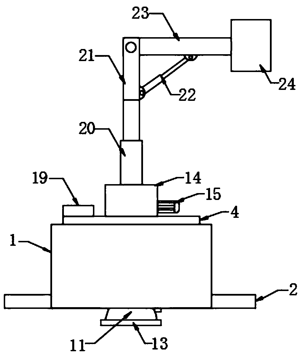
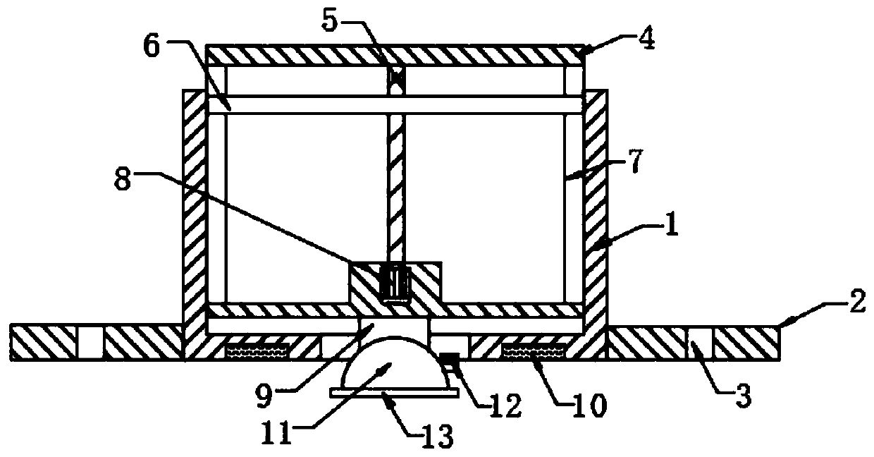
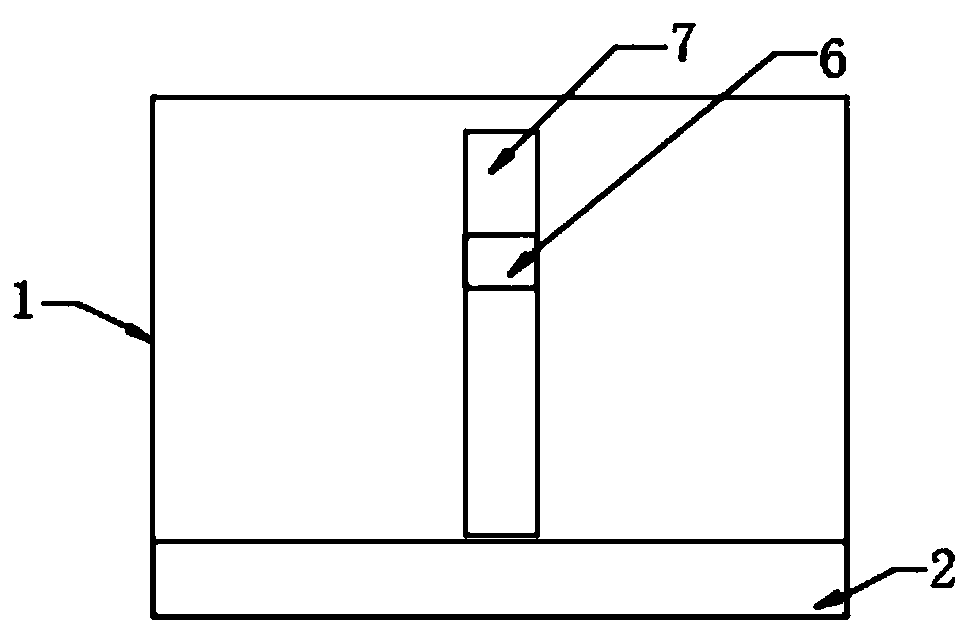
[0020] see Figure 1-5 , the present invention provides a technical solution: a network monitoring device, including a fixed box 1, a mounting plate 2, a power box 4, a screw rod 5, a limit rod 6, a groove 7, a lifting motor 8, a control box 9, an electromagnetic Iron 10, suction cup 11, mounting box 14, rotating motor 15, transmission rod 16, worm screw 17, worm wheel 18, control panel 19, the first electric telescopic rod 20, fixed rod 21, the second electri...


PUM


Abstract

The invention discloses a network monitoring device. The network monitoring device comprises a fixed box, mounting plates, a power box, a lead screw, a limiting rod, a groove, a lifting motor, a control box, electromagnets, a sucking disc, a mounting box, a rotary motor, a transmission rod, a worm, a worm gear, a control panel, a first electric telescopic pole, a fixed rod, a second electric telescopic pole, a supporting rod and a camera, wherein the bottom ends of the corresponding two sides of the fixed box are fixedly connected with the mounting plates; the bottom of the fixed box is symmetrically embedded and equipped with the electromagnets; the power box is arranged inside the fixed box; the lead screw is arranged inside the power box; and the top of the lead screw is rotatably connected to the top of the inner wall of the power box. According to the network monitoring device disclosed by the invention, the rotary motor, the worm gear and the worm are matched for use, so that angle adjustment of the camera is realized, all-around rotation of the camera can be realized, adjustability is strong, and large-range monitoring is convenient. The monitoring device is conveniently dismounted, so that the problem that the monitoring device is accumulated with dust and is difficult to clear while not used for a long time is avoided.

Description

technical field [0001] The invention relates to the technical field of monitoring devices, in particular to a network monitoring device. Background technique [0002] Surveillance camera is a semiconductor imaging device, which has the advantages of high sensitivity, anti-glare, small distortion, small size, long life, anti-vibration, etc. Surveillance cameras can be installed everywhere, whether outdoors or indoors. The current monitoring devices are generally It is fixed at a certain position, and multiple monitoring devices need to be installed when other places need to be monitored. Installing multiple monitoring devices is a waste of material, and it is difficult to disassemble when not in use. It is not easy to disassemble and assemble, and it is very inconvenient to use. Different materials for the installation part of the monitoring device require different installation methods. The installation method of the existing monitoring device is relatively fixed, and it is ...

Claims


Application Information

Patent Timeline
Patent Type & Authority Patents(China)
IPC IPC(8): F16M11/18F16M11/28F16M11/10H04N7/18
CPCF16M11/105F16M11/18F16M11/28H04N7/18
Inventor 王本勋
Owner 浙江中谷智业信息技术有限公司
Why Eureka
Try Eureka