Manipulator capable of rotating in multiple directions

A manipulator and one technology, applied in the field of manipulators, can solve the problems of complex manipulator structure, inability to realize multi-directional rotation, inconvenient manipulator maintenance and installation, etc., to achieve the effect of simple structure and rapid loading and unloading of circular workpieces.

Inactive Publication Date: 2017-05-10
沈越琦
View PDF0 Cites 0 Cited by
  • Summary
  • Abstract
  • Description
  • Claims
  • Application Information

AI Technical Summary

Problems solved by technology

[0004] There are many types of existing manipulators. In the forging industry, the manipulators used to clamp round forgings have different structures. Most of them cannot realize multi-directional rotation. At the same time, some manipulators have more complicated structures, which brings inconvenience to the maintenance and installation of the manipulators.

Method used


Image

  • Manipulator capable of rotating in multiple directions
  • Manipulator capable of rotating in multiple directions
  • Manipulator capable of rotating in multiple directions

Examples


Embodiment

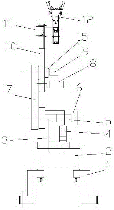
[0023] Example: see Figures 1 to 4 As shown, a manipulator that can rotate in multiple directions includes a first motor 4, a first reducer 3, a second motor 5 and a second reducer 6;

[0024] The junction box 2 is fixed on the base 1, the first reducer 3 is fixed on the junction box 2, the rotating shaft of the first motor 4 is fixed with the input shaft of the first reducer 3, and the output shaft of the first reducer 3 is fixed There is a second speed reducer 6, and the rotating shaft of the second motor 5 is fixed with the input shaft of the second speed reducer 6;

[0025] A boom 7 is fixed on the output shaft of the second speed reducer 6, and a hinge shaft 9 is formed or fixed on the boom 7. The small arm 10 is a hollow box, and the small arm 10 is inserted and sleeved on the hinge shaft 9. The third motor 8 is fixed on the small arm 10, a drive gear 13 is fixed on the rotating shaft of the third motor 8, a fixed gear 14 is fixed on the hinge shaft 9, the drive gear 1...


PUM


Abstract

Provided is a manipulator capable of rotating in multiple directions. A junction box is fixed on a base, and a first speed reducer 3 is fixed on the junction box; a rotating shaft of a first motor and an input shaft of the first speed reducer are fixed together, a second speed reducer is fixed on an output shaft of the first speed reducer, and a rotating shaft of a second motor and an input shaft of the second speed reducer are fixed together; a large arm is fixed on an output shaft of the second speed reducer, and a hinge shaft is formed on or fixed to the large arm; a small arm is a hollow box body, and the hinge shaft is inserted into the small arm in a sleeved mode; a third motor is fixed on the small arm, a driving gear is fixed on a rotating shaft of the third motor, and a fixed gear is fixed on the hinge shaft and engaged with the driving gear; and a compression nut is in threaded connection with the hinge shaft and presses the small arm. The manipulator is simple in structure, capable of rotating in multiple directions, and capable of rapidly achieving automatic opening and closing of the clamping arms, so that the effect of rapid feeding and discharging of circular workpieces is achieved.

Description

[0001] Technical field: [0002] The invention relates to the technical field of manipulators, in particular to a manipulator for clamping circular workpieces. [0003] Background technique: [0004] There are many types of existing manipulators. The manipulators used in the forging industry for clamping circular forgings have different structures, and most of them cannot realize multi-directional rotation. At the same time, some manipulators have more complicated structures, which brings inconvenience to the maintenance and installation of the manipulators. [0005] Invention content: [0006] The purpose of the present invention is to provide a multi-directional rotating manipulator in view of the deficiencies of the prior art. It has a simple structure and can realize multi-directional rotation. The effect of shaped workpieces. [0007] Technical solutions of the present invention are as follows: [0008] A manipulator capable of multi-directional rotation, comprising a f...

Claims


Application Information

Patent Timeline
Patent Type & Authority Applications(China)
IPC IPC(8): B65G47/90
CPCB65G47/904
Inventor 沈越琦
Owner 沈越琦
Why Eureka
Try Eureka