Flat-plate-type transverse flux permanent magnet synchronous linear generator

A linear generator and transverse magnetic flux technology, applied in the direction of electrical components, electromechanical devices, electric components, etc., can solve the problems of large cogging force and low space utilization rate, achieve small cogging force, simple magnetic circuit, and improve The effect on overall reliability

Active Publication Date: 2018-02-27
INST OF ELECTRICAL ENG CHINESE ACAD OF SCI
View PDF4 Cites 2 Cited by
  • Summary
  • Abstract
  • Description
  • Claims
  • Application Information

AI Technical Summary

Problems solved by technology

[0005] The purpose of the present invention is to overcome the shortcomings of the existing transverse flux permanent magnet linear generators such as low space utilization rate and large cogging force, and propose a flat plate type transverse flux permanent magnet synchronous linear generator

Method used


Image

  • Flat-plate-type transverse flux permanent magnet synchronous linear generator
  • Flat-plate-type transverse flux permanent magnet synchronous linear generator
  • Flat-plate-type transverse flux permanent magnet synchronous linear generator

Examples


Embodiment 1

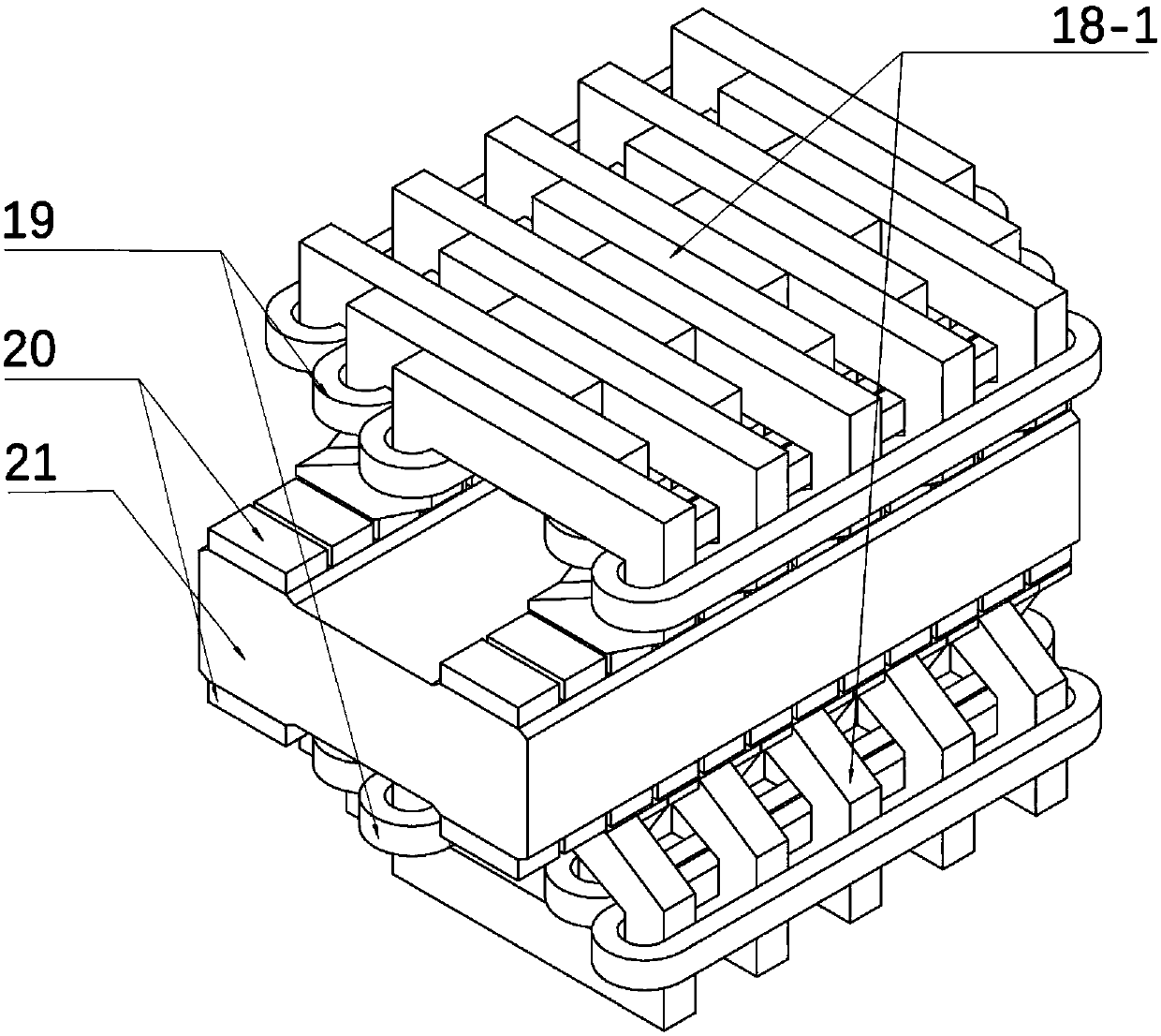
[0030] image 3 Shown is Embodiment 1 of the present invention that can be used in a bilateral transverse flux permanent magnet synchronous linear generator: a bilateral transverse flux permanent magnet synchronous linear generator. Two sets of transverse magnetic flux permanent magnet synchronous linear generator primary 18 mirror symmetrically placed. Two sets of racetrack-shaped windings 19 are wound on the primary tooth poles of the linear generator, secondary magnets 20 are evenly arranged on both sides of the secondary iron core 21, and the directions of magnetization between adjacent magnets are opposite. When the secondary moves at a certain speed, the flux linkage between the coils changes according to the sinusoidal law, thereby generating electric energy.

Embodiment 2

[0032] The transverse magnetic flux permanent magnet synchronous linear generator of the present invention can be used in a double-float floating direct-drive point-absorption wave energy power generation system. Figure 4 Shown is Embodiment 2: a double-float floating direct-drive point-absorption wave energy power generation system. Such as Figure 4 As shown, the double-floating floating direct-drive point-absorbing wave energy generation system floats on the sea as a whole, and the double-floating buoys 22 float on the sea. The out-of-phase primary iron core 18 of the transverse flux permanent magnet synchronous generator of the present invention is installed inside the floating buoy 22, the winding 19 is wound around the tooth pole body of the three-phase primary iron core, the surface of the magnetic steel 20 is attached to the surface of the secondary iron core 21, and the secondary The iron core 21 is connected to the damping float 24 through the connecting rod 23 . ...

Embodiment 3

[0035] The transverse flux permanent magnet synchronous linear generator of the present invention can be used in a direct-drive wave energy power generation system fixed on the seabed. Figure 5 Shown is Embodiment 3: a direct-drive point-absorption wave energy power generation system with the bottom fixed on the seabed. Such as Figure 5 As shown, the motor sealing casing 29 is fixed on the sea bed of the seabed, and the floating buoy 28 floats on the sea surface. The out-of-phase primary iron core 18 of the linear generator of the present invention is integrally fixed on the inner side of the motor casing 29 . The primary winding 19 is wound around the tooth pole body of the three-phase primary iron core, and the surface of the magnetic steel 20 is attached to the surface of the secondary iron core 21. Floats 28 are connected. After the secondary moves upwards, the return spring 30 can restore the secondary to its initial position. The top of the casing 29 is provided wi...


PUM


Abstract

Provided is a flat-plate-type transverse flux permanent magnet synchronous linear generator. The generator comprises flat-plate-type transverse flux primary pole iron cores, a flat-plate-type transverse flux secondary pole iron core, secondary pole magnetic steel and a racetrack winding; the secondary magnetic steel is flatly laid and arrayed on the surface of the flat-plate-type transverse flux secondary pole iron core in the z axis direction that a motor moves by adopting a surface-mount mode. A flat-plate-type transverse flux primary pole is mounted parallel to and opposite to the secondarymagnetic steel, and air gaps are formed between flat-plate-type transverse flux primary tooth pole shoes and the secondary magnetic steel; the racetrack winding winds around pole bodies of flat-plate-type transverse flux primary pole iron core tooth poles. The flat-plate-type transverse flux permanent magnet synchronous linear generator can be applied to direct-driving-type wave energy generationsystems.

Description

technical field [0001] The invention relates to a linear generator, in particular to a transverse flux permanent magnet synchronous linear generator. Background technique [0002] In the wave energy power generation system, there are two ways to extract the energy of the linear motion of the wave energy. One is to use a mechanical transmission device to convert the linear motion into a rotary motion, such as connecting a pneumatic system, a hydraulic system or a gearbox, etc., but the intermediate links are complicated. , reducing the reliability and conversion efficiency of the system. Second, use a linear generator. The method does not need any intermediate mechanism, and the structure is simple in this way, which improves the efficiency and reliability of the system. However, the power density of linear generator systems is generally lower than that of rotary motor systems. [0003] In order to improve the power density of permanent magnet linear motors, some scholars ...

Claims


Application Information

Patent Timeline
Patent Type & Authority Applications(China)
IPC IPC(8): H02K41/03
Inventor 邱书恒王海峰黄元峰艾程柳
Owner INST OF ELECTRICAL ENG CHINESE ACAD OF SCI
Why Eureka
Try Eureka