Mechanism for supporting large cylindrical workpieces

A cylindrical and workpiece technology, applied in the field of mechanisms supporting large cylindrical workpieces, can solve problems such as workpieces affecting machining accuracy and machining quality, and achieve the effects of avoiding deformation or falling off, improving construction efficiency, and ensuring structural strength.

Inactive Publication Date: 2018-03-09
黄生林
View PDF0 Cites 0 Cited by
  • Summary
  • Abstract
  • Description
  • Claims
  • Application Information

AI Technical Summary

Problems solved by technology

However, if the cylindrical workpiece is rolled on the support platform in the existing way, the workpiece will be offset and affect the machining accuracy, thereby affecting the machining quality

Method used


Image

  • Mechanism for supporting large cylindrical workpieces

Examples


Embodiment 1

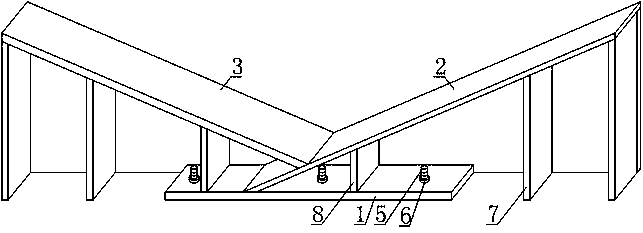
[0017] Such as figure 1 As shown, the mechanism for supporting a large cylindrical workpiece includes a bottom mounting plate 1, a first support plate 2, a second support plate 3 and a back reinforcement plate 4, wherein the bottom mounting plate 1 is arranged horizontally, and the first support plate 2 The left side is low and the right side is high, and its left end is fixedly connected to the upper surface of the bottom mounting plate 1. The second support plate 3 is left high and right is low, and its right end is fixedly connected to the upward slope of the first support plate 2. In this embodiment, the included angle between the first support plate 2 and the second support plate 3 is preferably 120°-140°.

[0018] The back reinforcing plate 4 of this embodiment is arranged on the rear side of the bottom mounting plate 1 , the first supporting plate 2 and the second supporting plate 3 and is fixedly connected with the three. In order to make the force transmission more b...

Embodiment 2

[0022] In order to avoid overturning when the large cylindrical workpiece is put on hold in this embodiment, this embodiment makes the following further limitations on the basis of Embodiment 1: this embodiment also includes a connecting screw 5 and a lock nut 6, wherein the connecting wire The rod 5 is arranged vertically and its lower end passes through the bottom mounting plate 1 and is embedded in the ground. When this embodiment is specifically set up, the bottom mounting plate 1 is formed with a plurality of positioning perforations that run through its upper and lower end faces, and any two adjacent positioning perforations are arranged at a certain distance in the transverse direction, and the connecting screw rod 5 passes through the positioning perforations. Through the bottom mounting plate 1 , each positioning through hole corresponds to a connecting screw 5 , and each connecting screw 5 is correspondingly provided with a locking nut 6 .

[0023] In this way, when ...


PUM


Abstract

The invention discloses a mechanism for supporting a large cylindrical workpiece, which includes a bottom mounting plate, a first supporting plate, a second supporting plate and a back reinforcement plate, the first supporting plate is arranged with a lower left side and a higher right side, and its left end is connected to the bottom mounting plate The upper end surface is fixedly connected, the second support plate is set with a high left and right low slope and its right end is fixedly connected with the upward slope of the first support plate, and the back reinforcement plate is arranged on the bottom mounting plate, the first support plate and the second support plate The rear side and is fixedly connected with the three. Both the first support plate and the second support plate are connected with the first positioning block on the downward slope, the lower end of the first positioning block is flush with the lower end surface of the bottom mounting plate, between the first support plate and the bottom mounting plate, the second A second positioning block is connected between the two support plates and the bottom mounting plate. The overall structure of the present invention is simple, easy to realize, and low in cost, and when the present invention is applied, it can support and position large cylindrical workpieces, and can avoid random rolling of large cylindrical workpieces.

Description

technical field [0001] The invention relates to a support structure, in particular a mechanism for supporting large cylindrical workpieces. Background technique [0002] When processing a large cylindrical workpiece, it is often necessary to move and roll the workpiece to change the processing part of the workpiece, so as to realize the overall processing of the workpiece. In order to facilitate the transportation of workpieces, people usually set a supporting platform on the workpiece conveying device, and the workpiece is supported by the supporting platform, and when the workpiece needs to roll, the cylindrical workpiece is controlled to roll on the supporting platform, so as to realize the processing position on the circumference of the workpiece. change. However, if the cylindrical workpiece is rolled on the supporting table in the existing method, the workpiece will be offset, which will affect the machining accuracy, thereby affecting the machining quality. Content...

Claims


Application Information

Patent Timeline
Patent Type & Authority Applications(China)
IPC IPC(8): B23Q1/03
CPCB23Q1/032
Inventor 黄生林
Owner 黄生林
Why Eureka
Try Eureka