A Foil Positioning, Cutting and Forming Device

A forming device and foil technology, applied in transportation and packaging, thin material handling, sending objects, etc., can solve the problems of foil surface flattening, positioning cutting, adverse effects, etc., to reduce adverse effects and smooth the surface , the effect of improving efficiency

Active Publication Date: 2021-12-10
扬州君品电子科技有限公司
View PDF16 Cites 0 Cited by
  • Summary
  • Abstract
  • Description
  • Claims
  • Application Information

AI Technical Summary

Problems solved by technology

The foil cutting machine currently used in the factory can cut the rolled foil into the required small pieces of foil, but the foil cutting efficiency is low, and it cannot be positioned and cut when cutting the foil, which is easy to cause foil The edge of the foil cutting is not smooth, which will have a negative impact on the later use. At the same time, the existing foil cutting machine does not have the function of flattening the surface of the cut foil. Flattening process is performed to increase the process of foil processing

Method used


Image

  • A Foil Positioning, Cutting and Forming Device
  • A Foil Positioning, Cutting and Forming Device
  • A Foil Positioning, Cutting and Forming Device

Examples


Embodiment 1

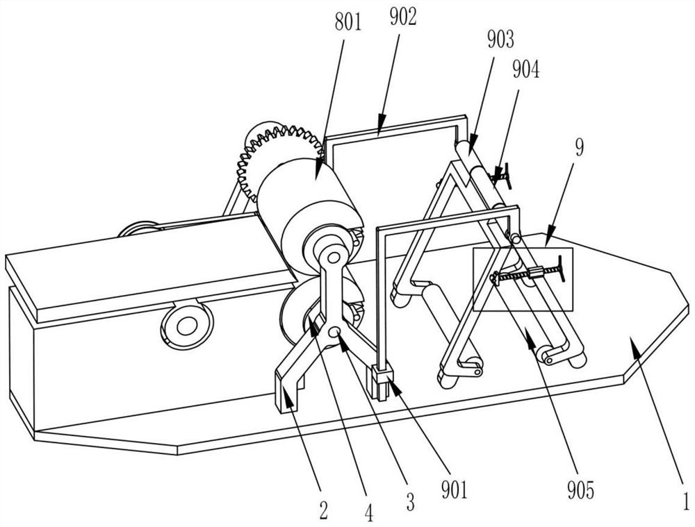
[0024] A foil positioning truncation forming device, such as Figure 1-8 As shown, it includes a base plate 1, a bracket 2, a rotating shaft 3, a fixed cam 4, a gear 5, a mounting frame 6, a driving motor 7, a cutting mechanism 8 and a foil clamping mechanism 9, and the upper side of the base plate 1 is fixedly installed with Two supports 2 that are symmetrically arranged, two rotating shafts 3 are installed by bearings on the two supports 2, two fixed cams 4 are fixedly installed on the two supports 2 and the two rotating shafts 3 pass through the circular holes in the middle of the fixed cam 4, and the two One end of the rotating shaft 3 is equipped with a gear 5 and the two gears 5 mesh with each other. The mounting frame 6 is fixedly mounted on the upper side of the bottom plate 1 and is close to one of the brackets 2. The driving motor 7 is fixedly mounted on the mounting frame 6 The upper side of the drive motor 7 and the output shaft of the drive motor 7 are fixedly con...

Embodiment 2

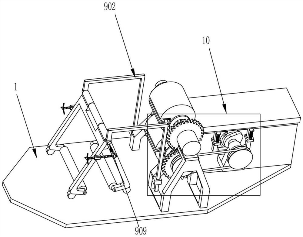
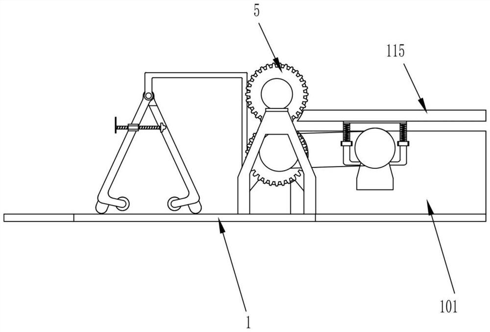
[0030] On the basis of Example 1, such as Figure 2-3 and Figure 7-8 As shown, it also includes a conveying mechanism 10 for conveying the cut foil. The conveying mechanism 10 is installed on the upper side of the bottom plate 1 and is close to the cutting mechanism 8. The conveying mechanism 10 includes a support seat 101, a fixed Plate 102, power transmission shaft 103, first pulley 104, second pulley 105, transmission belt 106 and push wheel 107, described support base 101 is fixedly installed on the upper side of base plate 1 and offers a circular recess on support base 101 slot, the fixed plate 102 is fixedly installed on one side of the support base 101 and is located above the bottom plate 1, the transmission shaft 103 is mounted on the fixed plate 102 through a bearing, and the first pulley 104 is installed on the drive shaft 103 One end, the second pulley 105 is installed on one end of the other rotating shaft 3, a transmission belt 106 is connected between the firs...


PUM


Abstract

The invention relates to the technical field of foil processing, in particular to a foil positioning, cutting and forming device. The object of the present invention is to provide a foil positioning and cutting operation that performs cutting and truncating during the conveying process of the foil, and can realize continuous positioning and truncating operations on rolled foils, and has the functions of foil cutting and flattening Forming device. The technical solution is: a foil positioning, cutting and forming device, including a base plate, a bracket, a rotating shaft, a fixed cam, a gear, a mounting frame and a driving motor, etc.; one side of the base plate is fixed with two symmetrically arranged brackets, two Two rotating shafts are installed on the support through bearings. In the present invention, two rollers are used to lift the coiled foil on the bottom plate and limit it, which can prevent one end of the foil from rolling freely during transmission and cutting, and the fixed cam cooperates with the toggle lever The job enables rapid cutting and truncation of the foil while it is being conveyed.

Description

technical field [0001] The invention relates to the technical field of foil processing, in particular to a foil positioning, cutting and forming device. Background technique [0002] Foil generally refers to metal foil, which is a thin metal sheet extended from metal. [0003] In order to facilitate storage and transportation, the foil will be made into rolls during production, so when the foil is to be used later, it is necessary to cut the rolled foil into small pieces of foil. The foil cutting machine currently used in the factory can cut the rolled foil into the required small pieces of foil, but the foil cutting efficiency is low, and it cannot be positioned and cut when cutting the foil, which is easy to cause foil The edge of the foil cutting is not smooth, which will have a negative impact on the later use. At the same time, the existing foil cutting machine does not have the function of flattening the surface of the cut foil. The flattening process increases the p...

Claims


Application Information

Patent Timeline
Patent Type & Authority Patents(China)
IPC IPC(8): B65H35/08
CPCB65H35/08B65H2701/173
Inventor 江伟
Owner 扬州君品电子科技有限公司
Why Eureka
Try Eureka