
Lawn mower and operating method thereof
A lawn mower and lawn technology, which is applied to harvesters, cutters, agricultural machinery and implements, etc., can solve the problems of motor burnout, failure to meet maintenance personnel, and large resistance of rotary blades, so as to enhance operational reliability and avoid motor failure. burnt effect
- Summary
- Abstract
- Description
- Claims
- Application Information
AI Technical Summary
Problems solved by technology
Method used
Image

Examples
Embodiment Construction
[0022] The present invention will be further described below in conjunction with the accompanying drawings.
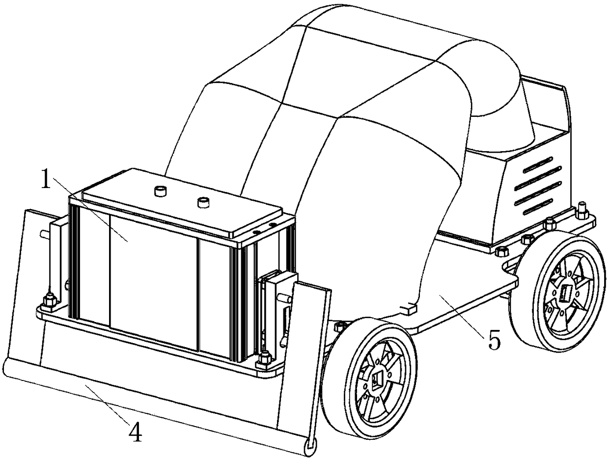
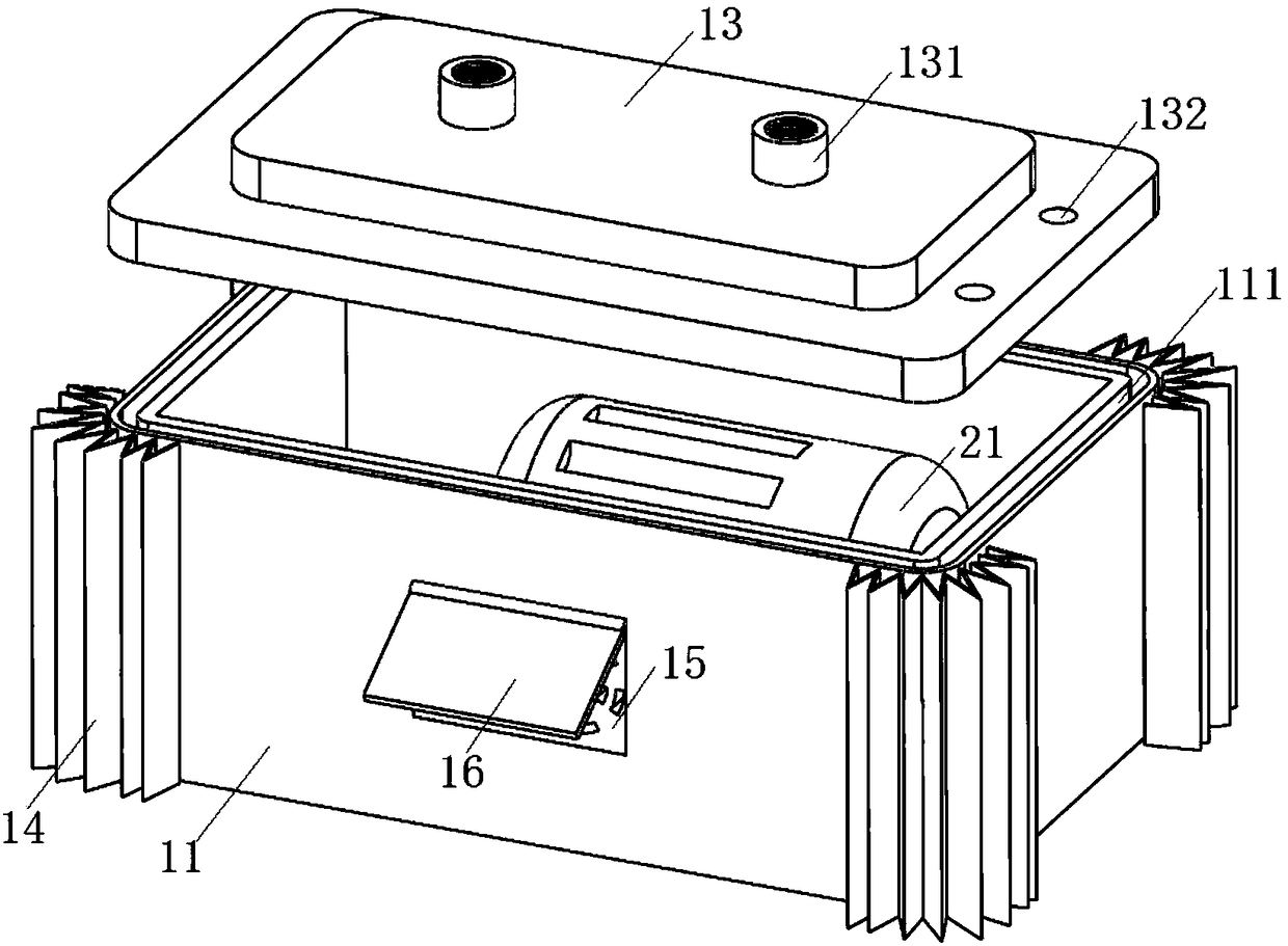
[0023] as attached figure 1 Shown, a kind of lawn mower comprises power unit 1, cutting device, suction device, rolling brush 4, working platform 5 and spraying device 6; The power input end of the device 6 is connected; the cutting device is installed at the bottom of the working platform 5; the inlet of the suction device is arranged above the cutting device; the rolling brush 4 is installed at the tail of the working platform 5; as attached figure 2 As shown, the power unit 1 includes a protective shell 11; the protective shell 11 is installed on the upper end of the working platform 5; the cutting device includes a motor 21, a transmission shaft and a rotary vane; the motor 21 is arranged inside the protective shell 11; The motor 21 drives the rotary vane to rotate through the transmission shaft; the top cover 13 is provided on the top of the protective shell 11;...
PUM
 Abstract
Description
Claims
Application Information