Novel arch frame quantitative yielding energy consumption connection device and manufacturing method thereof

A connecting device and a new type of technology, which can be used in vertical shaft equipment, earthwork drilling, wellbore lining, etc., can solve the problems of insufficient support strength, low working resistance, unsafe operators, etc., so as to reduce casualties and economic losses, reduce Construction cost and construction period, the effect of convenient replacement process

Inactive Publication Date: 2018-07-24
WUHAN UNIV
View PDF0 Cites 2 Cited by
  • Summary
  • Abstract
  • Description
  • Claims
  • Application Information

AI Technical Summary

Problems solved by technology

Among them, U-shaped steel arch support is the most commonly used passive support method in soft rock roadways. It provides passive radial support force and directly acts on the surface of the roadway surrounding rock to balance the deformation pressure of the surrounding rock and restrain the surrounding rock. However, there are many problems in the support of U-shaped steel arches: ① Insufficient support strength, ② Low working resistance, ③ The support capacity cannot be fully exerted, which seriously reduces the utilization rate of materials, and the support effect is good. ④The concrete-filled steel tube arch frame is a support form with high bearing capacity, certain shrinkability, convenient construction, and good mechanical properties; but there are also the following problems: ①Circular cross-section The contact area between the concrete-filled steel tube arch and the surrounding rock surface is small, which is likely to cause stress concentration. ②The cost is relatively high. ③Lack of special underground installation equipment. ④The weight of the arch frame is relatively large. It will make the operator feel unsafe; compared with the above-mentioned support methods, the pressure arch support has better engineering applicability and safety, and can greatly reduce the occurrence of disasters. In the past decades of engineering practice , people have manufactured a lot of support materials and support structures with the function of yielding pressure, and improved the original rigid support structure to increase the shrinkability of the support
However, most of the yielding arch supports used in underground engineering now only consider the problem of deformation, and the yielding arch supports can only perform free yielding, which can realize quantitative yielding of energy consumption of steel structures in the work of arch supports device not reported

Method used


Image

  • Novel arch frame quantitative yielding energy consumption connection device and manufacturing method thereof
  • Novel arch frame quantitative yielding energy consumption connection device and manufacturing method thereof
  • Novel arch frame quantitative yielding energy consumption connection device and manufacturing method thereof

Examples


Embodiment 1

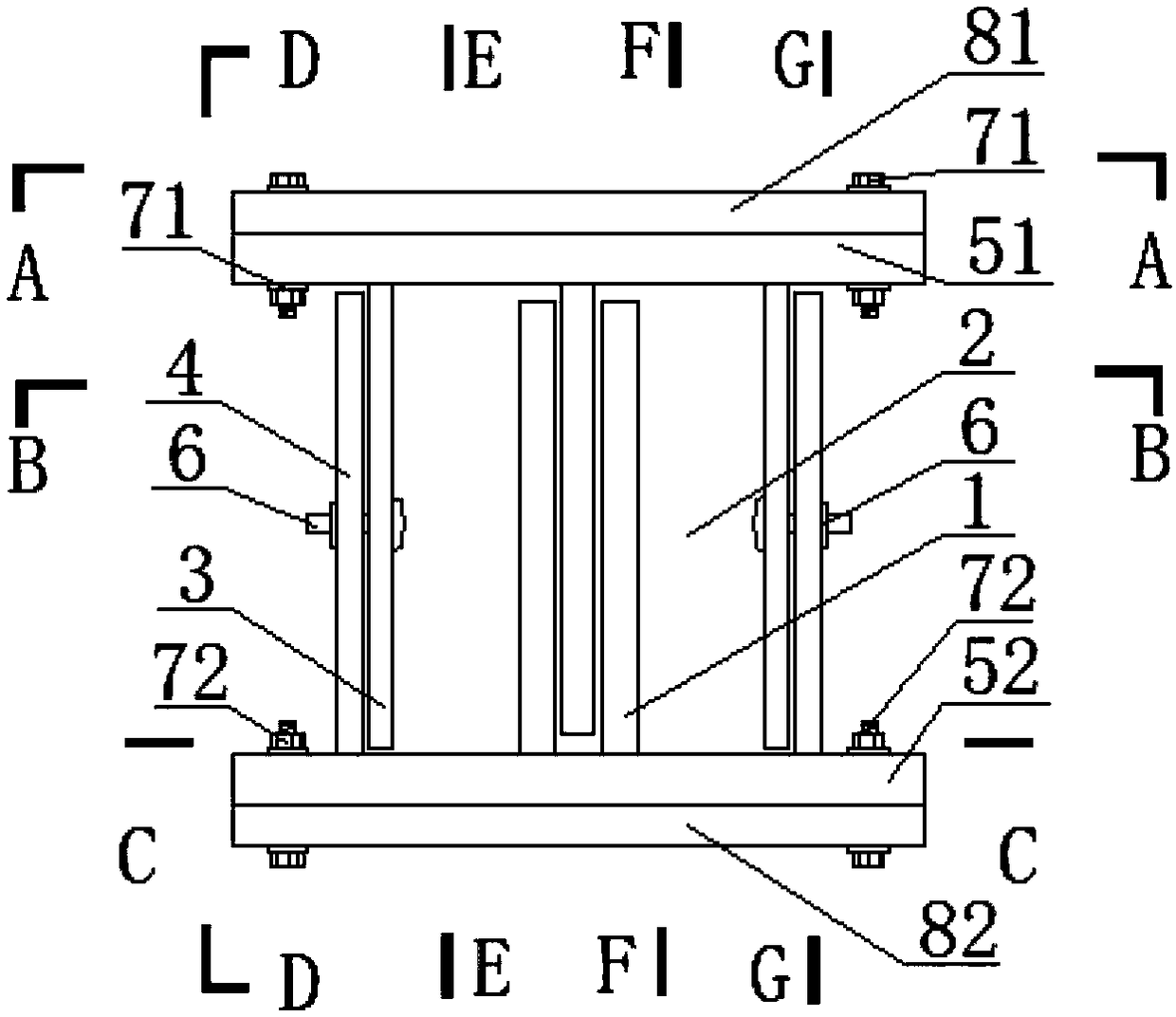
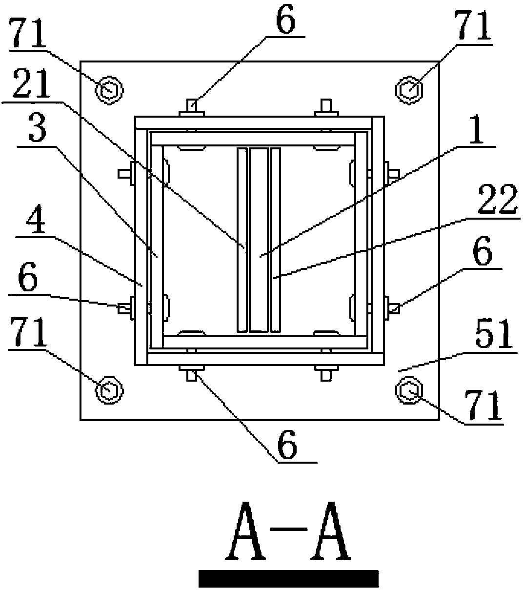
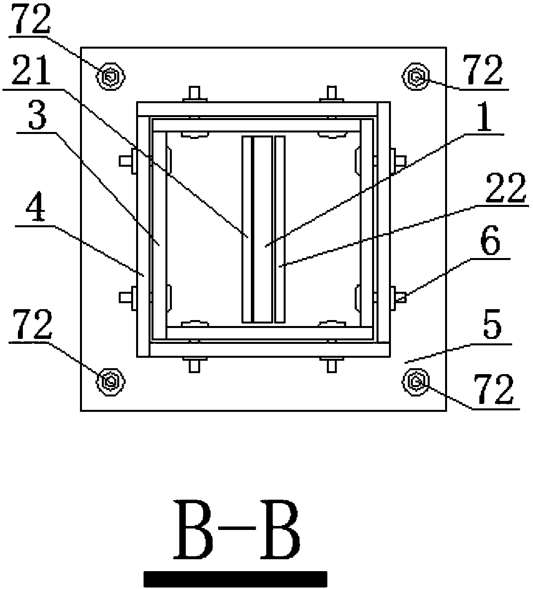
[0045] Refer to as Figure 1 to Figure 11 , a quantitative pressure loss energy connection device, comprising a main core component 1, a secondary core component 1 21, a secondary core component 2 22, an upper connecting device 3, a lower connecting device 4, an upper top plate 51, a lower bottom plate 52, and joints Connecting device 6, sliding hole 1 31, sliding hole 2 41, upper connecting bolt 71, lower connecting bolt 72, upper arch structure plate 81, lower arch structure 82;

[0046] The main core component 1 is fixedly connected to the upper top plate 51, and the secondary core component one 21 and secondary core component two 22 are connected to the lower bottom plate 52; the primary core component, secondary core component one and secondary core component Two parallel settings;

[0047] The upper connecting device 3 is connected to the upper top plate 51, the lower connecting device 4 is connected to the lower base plate 52, the first sliding hole 31 is set on the up...

Embodiment 2

[0050] A method for manufacturing a novel arch quantitatively allowing pressure loss energy connection device, comprising the following steps:

[0051] (1) Reasonable selection of materials used in quantitatively allowing pressure loss energy connection devices;

[0052] (2) Processing each component of the pressure-releasing connection device, the main core component and the secondary core component are subjected to precise machining, and the surface should be sandblasted to make the surface more frictional;

[0053] (3) The main core component is fixedly connected to the upper roof, and the secondary core component 1 and secondary core component 2 are connected to the lower floor; the primary core component, secondary core component 1 and secondary core component 2 are arranged in parallel;

[0054] (4) The upper connecting bolts and the lower connecting bolts are respectively arranged on the upper top plate and the lower bottom plate;

[0055] (5) The joint connection devi...


PUM


Abstract

The invention provides a novel arch frame quantitative yielding energy consumption connection device and a manufacturing method thereof, wherein a major core component is fixedly connected with an upper part top plate; a first minor core component and a second minor core component are connected with a lower part bottom plate; the major core component, the first minor core component and the secondminor core component are in parallel arrangement; an upper part connecting mechanism is connected onto the upper part top plate; a lower part connecting device is connected onto a lower part bottom plate; first and second slide holes are formed in the upper and lower part connecting devices; a joint connecting device is fixed in the first slide hole and the second slide hole; the upper part connecting device, the upper part top plate, the lower part connecting device and the lower part bottom plate are spliced to form a boxing structure of the quantitative yielding energy consumption connection device; then, through an upper part connecting screw bolt and a lower part connecting screw bolt, the boxing structure of the quantitative yielding energy consumption connection device is connectedwith an upper part arch frame structure plate and a lower part arch frame structure of a supporting main structure. The novel arch frame quantitative yielding energy consumption connection device hasthe advantages that the structure is simple; the installation is convenient; the yielding is in time; the yielding quantity is manually controllable.

Description

technical field [0001] The invention relates to the technical field of underground engineering structures, in particular to a novel arch frame quantitative yielding pressure consumption energy connection device and a manufacturing method thereof. Background technique [0002] The 21st century is a new era of global human underground space development. my country is the country with the largest scale, quantity and difficulty of underground space development in the world, involving transportation, water conservancy and hydropower, energy and other national infrastructure construction fields. As the construction of tunnels and underground projects in my country has entered an unprecedented period of prosperity, opportunities and challenges coexist. During the construction of tunnels and underground projects, especially in deep underground spaces and complex strata, large deformations of surrounding rocks, rockbursts, landslides, and outbursts are often faced. Water gushing mud ...

Claims


Application Information

Patent Timeline
Patent Type & Authority Applications(China)
IPC IPC(8): E21D11/22
CPCE21D11/22
Inventor 杭振园朱汉华吴志军
Owner WUHAN UNIV
Why Eureka
Try Eureka