A multi-point adaptive jacking device for steel box girder

A multi-point self-adaptive, jacking device technology, applied in the direction of bridges, bridge construction, erection/assembly of bridges, etc., can solve the problems of affecting work efficiency, wasting time, and low requirements, so as to improve work efficiency, facilitate use, and ensure The effect of stability

Active Publication Date: 2019-06-18
CHONGQING THREE GORGES UNIV
View PDF6 Cites 0 Cited by
  • Summary
  • Abstract
  • Description
  • Claims
  • Application Information

AI Technical Summary

Problems solved by technology

[0008] At present, multi-point jacking has low requirements on jacking equipment and is widely used for easy control. However, in the initial stage, due to the light weight of the steel box girder, the combination of horizontal jacks and vertical jacks for jacking is insufficient due to insufficient friction. It is difficult to drive the steel box girder to move. Usually, in order to increase the friction during the construction process, it is generally used to add heavy objects on the steel box girder in the early stage to increase the friction by increasing the weight. However, in this way, heavy objects will have a certain impact on the overall operation during the construction process, and a series of operations of placing heavy objects and then removing them is also a waste of time and affects work efficiency

Method used


Image

  • A multi-point adaptive jacking device for steel box girder
  • A multi-point adaptive jacking device for steel box girder
  • A multi-point adaptive jacking device for steel box girder

Examples


Embodiment

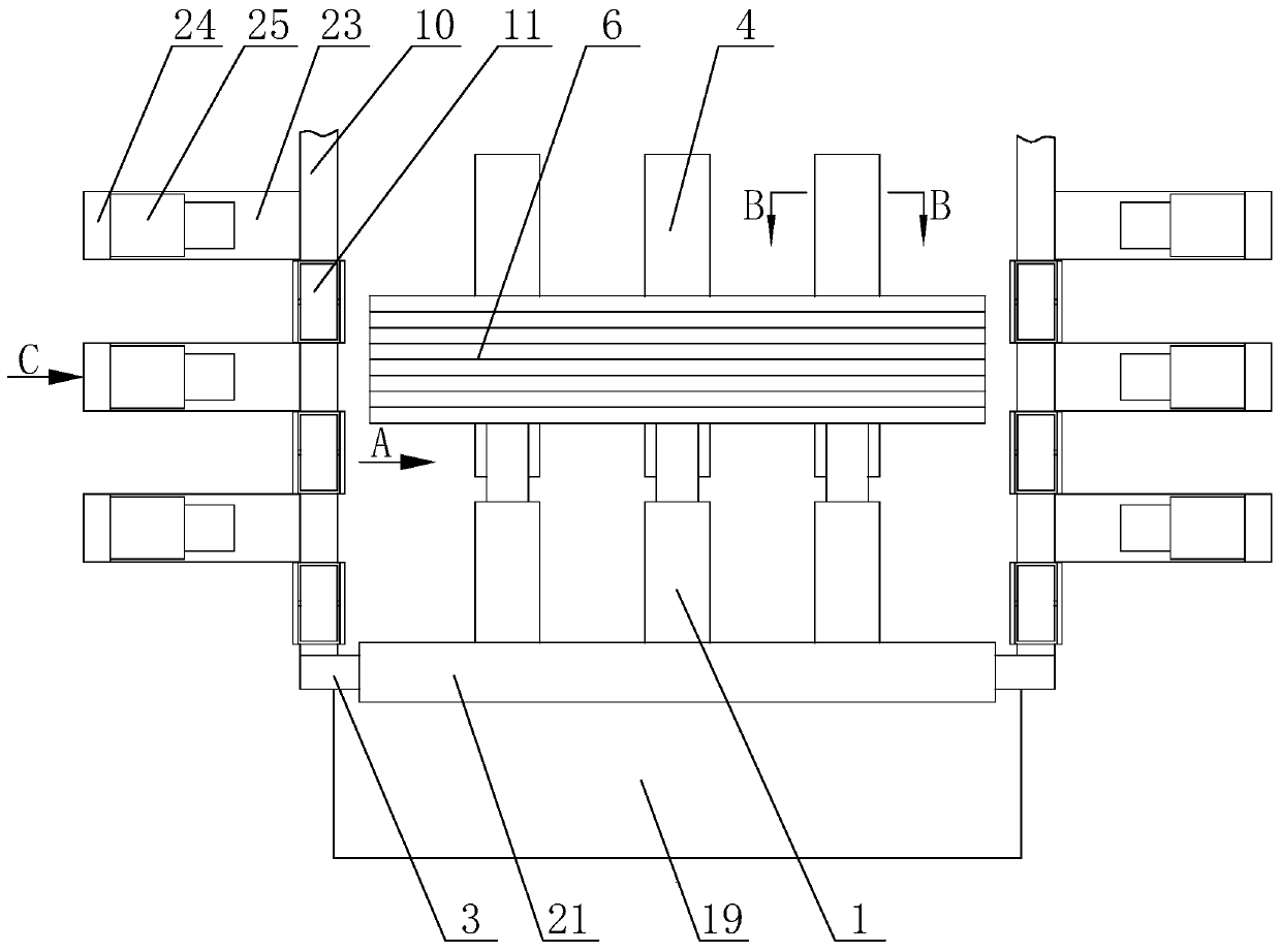
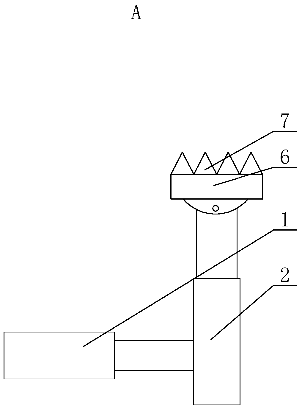
[0034] A multi-point self-adaptive jacking device for a steel box girder, comprising a horizontal jack 1 and a vertical jack 2, one end of the horizontal jack 1 is fixedly connected to the vertical jack 2, and the other end of the horizontal jack 1 is fixed Installed on the riser 3, the rear portion of the riser 3 is provided with the top of the first support plate 19 connected obliquely, and the bottom end of the first support plate 19 is fixedly connected with one end of the bottom plate 20, The other end of the base plate 20 is fixedly connected to the bottom of the riser 3, the top of the riser 3 is provided with a buffer plate 21, the height of the buffer plate 21 is lower than that of the auxiliary pulley 11, and the buffer plate 21 is lower than the height of the auxiliary pulley 11. A third shock absorber 22 is arranged between the plate 21 and the top of the vertical plate 3, the bottom of the vertical jack 2 is located in the chute 4, the bottom of the vertical jack 2...


PUM


Abstract

The invention provides a multi-point self-adaptive jacking-pushing device for a steel box girder. The multi-point self-adaptive jacking-pushing device comprises a horizontal jack and a vertical jack,one end of the horizontal jack is fixedly connected with the vertical jack, and the other end of the horizontal jack is fixedly mounted on a vertical plate; the lower portion of the vertical jack is located in a sliding groove, the bottom of the vertical jack is connected with a sliding block, the top end of the vertical jack is provided with a bearing plate, and the top end of the vertical jack is connected with the bearing plate in a hinged mode; a plurality of protruding blocks are evenly arranged on the bearing plate, and grooves are formed in the positions, corresponding to the protrudingblocks, of the bottom of the steel box girder; the protruding blocks and the grooves can be matched in an inserting-connection mode; and two vertical steel box girder receiving plates are arranged onthe two sides of the vertical plate correspondingly, the top ends of the steel box girder receiving plates are provided with a plurality of auxiliary pulleys, and the auxiliary pulleys can make contact with the steel box girder. According to the multi-point self-adaptive jacking-pushing device for the steel box girder, the bearing plate is additionally arranged, and the protruding blocks on the bearing plate are matched with the grooves in the steel box girder so that the steel box girder can effectively move under the matched action of the horizontal jack and the vertical jack, heavy objectsdo not need to be additionally arranged, and the working efficiency is improved effectively.

Description

technical field [0001] The invention belongs to the field of bridge construction, in particular to a multi-point self-adaptive pushing device for a steel box girder. Background technique [0002] With the continuous development of society, people's living standards and quality are also constantly improving, and bridge construction is also undergoing tremendous changes. Since Leonhardt and Professor Bauer of Dewei first used the jacking method on the Ager Bridge in Austria in 1959, the number of bridges constructed by the jacking method in countries around the world has been increasing. [0003] The jacking method construction is to set up a prefabricated field behind the abutment along the bridge axis direction, and set up steel guide beams, temporary piers, slideways, and horizontal jack force-applying devices. Specifically, the prefabricated concrete beam sections are segmented, connected into a whole with longitudinal prestressed tendons, the beams are pushed out section...

Claims


Application Information

Patent Timeline
Patent Type & Authority Patents(China)
IPC IPC(8): E01D21/00
CPCE01D21/00
Inventor 闫磊刘芳平苗秀鹏刘路杨茂
Owner CHONGQING THREE GORGES UNIV
Why Eureka
Try Eureka