
Method for extracting fault signal feature information of aero-engine rotor system
A technology for aero-engine and system failures, which is applied in the direction of engine testing, machine/structural component testing, measuring devices, etc. Problems such as single means
- Summary
- Abstract
- Description
- Claims
- Application Information
AI Technical Summary
Problems solved by technology
Method used
Image

Examples
Embodiment example
[0072] An implementation case of the method for extracting characteristic information of the fault signal of the aeroengine rotor system, including the following process:
[0073] The first step is to collect the rubbing vibration signal of the aero-engine rotor; through the eddy current displacement sensor, select 1000 sets of rubbing vibration signal data samples of the aero-engine rotor at a speed of 2000r / min, and set the sampling frequency of the signal to 1000Hz;
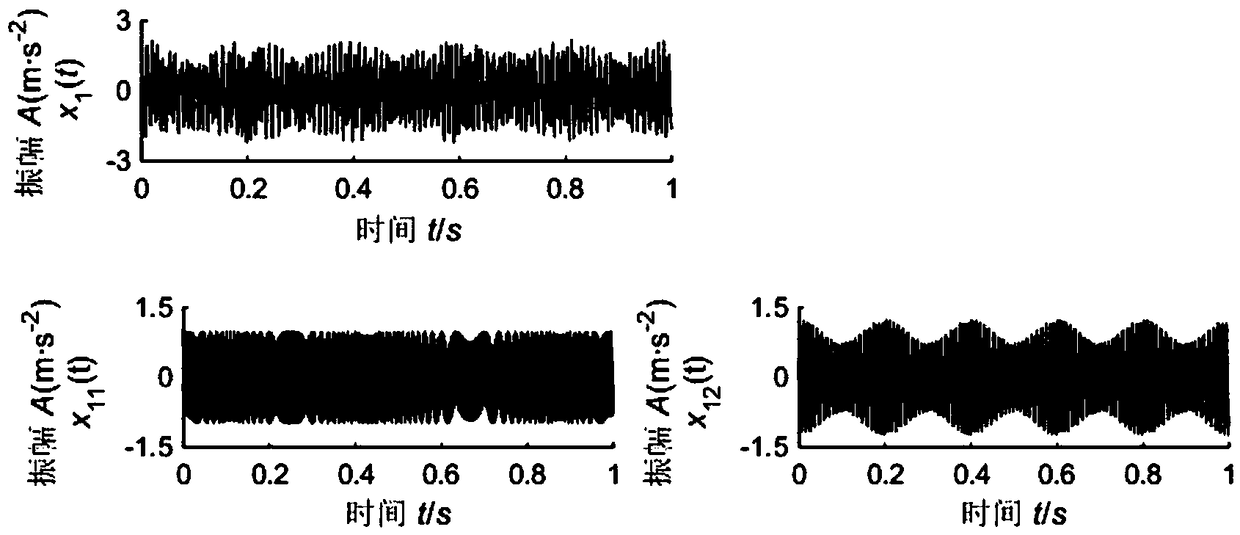
[0074] by formula Construct FM and AM timing simulation signal x 1 (t), simulated signal x 1 (t) contains a non-linear frequency modulation signal x 11 (t) and a frequency-modulated amplitude-modulated signal x with a certain period 12 (t), the sampling frequency of the set signal is 1000Hz;
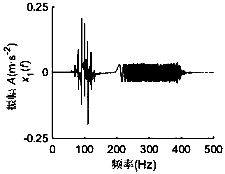
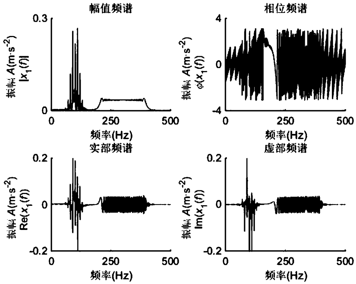
[0075] signal x 1 The time-domain waveform of (t) is as follows figure 1 shown. Among them, the signal x 1 The waveform diagram of (t) presents complex waveform pulse characteristics without significant periodic...
PUM
 Abstract
Description
Claims
Application Information