A portable design drawing display stand for industrial design

A technology of industrial design and design drawings, which is applied in applications, display hangers, household appliances, etc. It can solve the problems of inapplicable display methods and large space occupation, so as to avoid the small number of displays, large occupied area, and The effect of increasing the number of impressions

Active Publication Date: 2019-11-15
台州屹捷数控机床股份有限公司
View PDF6 Cites 0 Cited by
  • Summary
  • Abstract
  • Description
  • Claims
  • Application Information

AI Technical Summary

Problems solved by technology

[0005] Aiming at the deficiencies of the prior art, the present invention provides a portable design drawing display stand for industrial design, which solves the problem that the industrial design drawing hanger in the prior art takes up a lot of space, and the tiling display method is not suitable for displaying a large number of drawings. The problem

Method used


Image

  • A portable design drawing display stand for industrial design
  • A portable design drawing display stand for industrial design
  • A portable design drawing display stand for industrial design

Examples


Embodiment 1

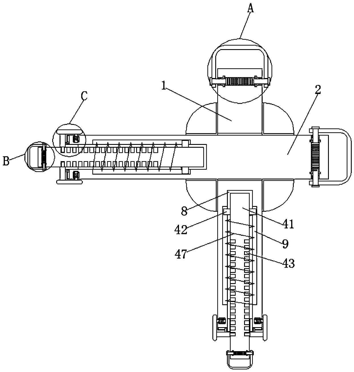
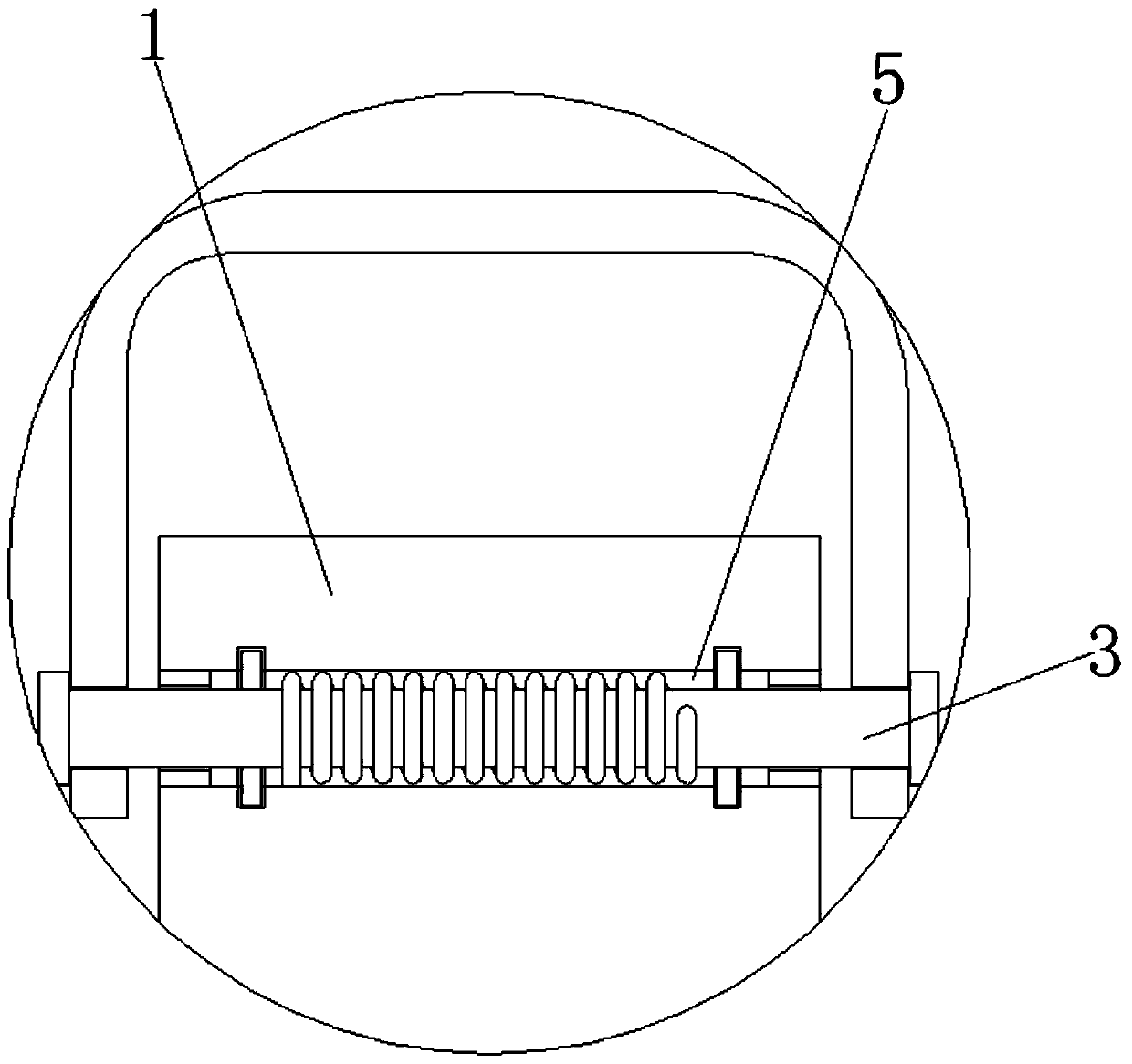
[0034] Such as Figure 1-5As shown, a portable design drawing display stand for industrial design includes a first fixed column 1 and a second fixed column 2, a first clamping mechanism 3 is arranged at one end of the top of the first fixed column 1, and a first clamping mechanism 3 is arranged at the bottom of the first fixed column 1. One end of the first fixed column 1 is provided with an extension mechanism 4, and one end of the top of the first fixed column 1 is provided with a first rotation hole 5 communicating with the left and right sides thereof, and the two sides of the inner cavity of the first rotation hole 5 are symmetrically provided with a first stop ring 6, The two ends of the four sides of the inner wall of the first rotating hole 5 are symmetrically provided with an annular limiting groove 7, the middle of the bottom of the first fixed column 1 is provided with a first moving groove 8, and the middle of the first moving groove 8 inner wall is symmetrically pr...

Embodiment 2

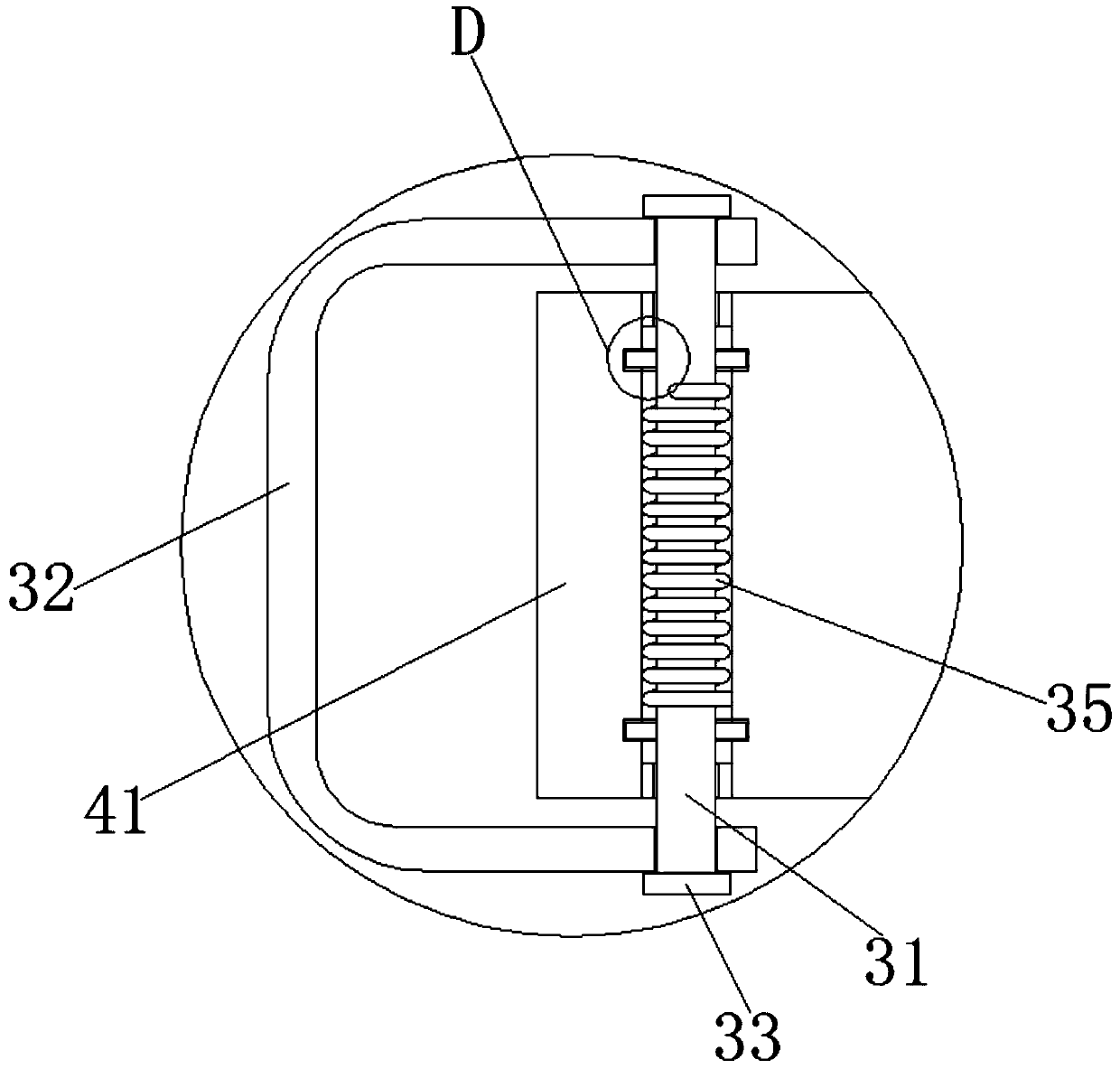
[0036] On the basis of Embodiment 1, the first clamping mechanism 3 includes a support rod 31, the top of the support rod 31 is provided with a clamping rod 32, and the two ends of the support rod 31 are symmetrically fixedly connected with a clamping cap 33, and the top of the support rod 31 is connected to the top of the support rod 31. Both sides of the bottom are fixedly connected with limiting blocks 34 symmetrically, and a torsion spring 35 is sleeved in the middle of the support rod 31 .

Embodiment 3

[0038] On the basis of Embodiment 1-2, the support rod 31 is arranged inside the first rotation hole 5, and the two ends of the support rod 31 respectively pass through the first limit rings 6 on both sides and extend to the outside of the first fixed column 1 , the support rod 31 fits with the first limit ring 6 .


PUM


Abstract

The invention discloses a light design drawing show shelf used for industrial design. The light design drawing show shelf used for industrial design comprises a first fixing column and a second fixingcolumn. One end of the top of the first fixing column is equipped with a first clamping mechanism. One end of the bottom of the first fixing column is provided with an extension mechanism. One end atthe top of the first fixing column is equipped with a first rotary hole communicating with left and right sides of the first fixing column. Two sides of an inner cavity of the first rotary hole are symmetrically equipped with first limiting rings. Two ends of four sides of the inner wall of the first rotary hole are symmetrically provided with annular limiting grooves. The light design drawing show shelf used for industrial design can fix one corner and two sides of a design drawing. The design drawing can be stably displayed by a triangular stabilizing principle. The problem that a conventional show board occupies a large area is avoided. Additionally, the design drawing is convenient to pick up and observed finely. Therefore, the number of displayed design drawings placed in a laminatedmanner is further increased. Therefore, the conventional show board can display a great number of drawings in a horizontally-laying manner.

Description

technical field [0001] The invention relates to the technical field of industrial design tools, in particular to a portable design drawing display stand for industrial design. Background technique [0002] In the teaching of industrial design, the teacher needs to combine the design drawings to explain, so in the teaching process, the design drawings need to be hung on the hanging board for teaching. For convenience, usually use transparent tape to fix the design drawings on the hanging board. On the board, although the operation is simple, this method has many disadvantages: the design drawings are not convenient to move; the transparent tape moves on the drawings, and there are great defects in the use time. [0003] In order to improve the existing technology, people have carried out long-term exploration and proposed various solutions. For example, the application of Chinese Patent Publication No. CN207120585U proposes a hanger for industrial design drawings, which incl...

Claims


Application Information

Patent Timeline
Patent Type & Authority Patents(China)
IPC IPC(8): A47B97/02A47F5/10A47F7/14
CPCA47B97/02A47F5/10A47F7/142
Inventor 孔令荣赵大全贺健赵文浩赵文晓
Owner 台州屹捷数控机床股份有限公司
Why Eureka
Try Eureka