Fabricated two-stage retaining wall structure

A retaining wall and prefabricated technology, applied to underwater structures, infrastructure engineering, artificial islands, etc., can solve the problem of large space occupied by sidewalks behind walls, small space occupied by sidewalks, and hard structures of retaining walls Excessive exposure and other problems, to achieve the effect of maintaining overall structural stability and thin thickness

Pending Publication Date: 2019-04-09
SHANGHAI WATER ENG DESIGN & RES INST
View PDF0 Cites 0 Cited by
  • Summary
  • Abstract
  • Description
  • Claims
  • Application Information

AI Technical Summary

Problems solved by technology

[0005] The technical problem to be solved by the present invention: Aiming at the problems that the hard structure of the retaining wall is exposed more and the sidewalk behind the wall takes up a lot of space in the traditional retaining wall structure, it is necessary to provide a method that avoids excessive exposure of the hard structure of the retaining wall and prevents pedestrians from walking. Prefabricated two-stage retaining wall structure with small road footprint and high overall stability

Method used


Image

  • Fabricated two-stage retaining wall structure
  • Fabricated two-stage retaining wall structure
  • Fabricated two-stage retaining wall structure

Examples


Embodiment 1

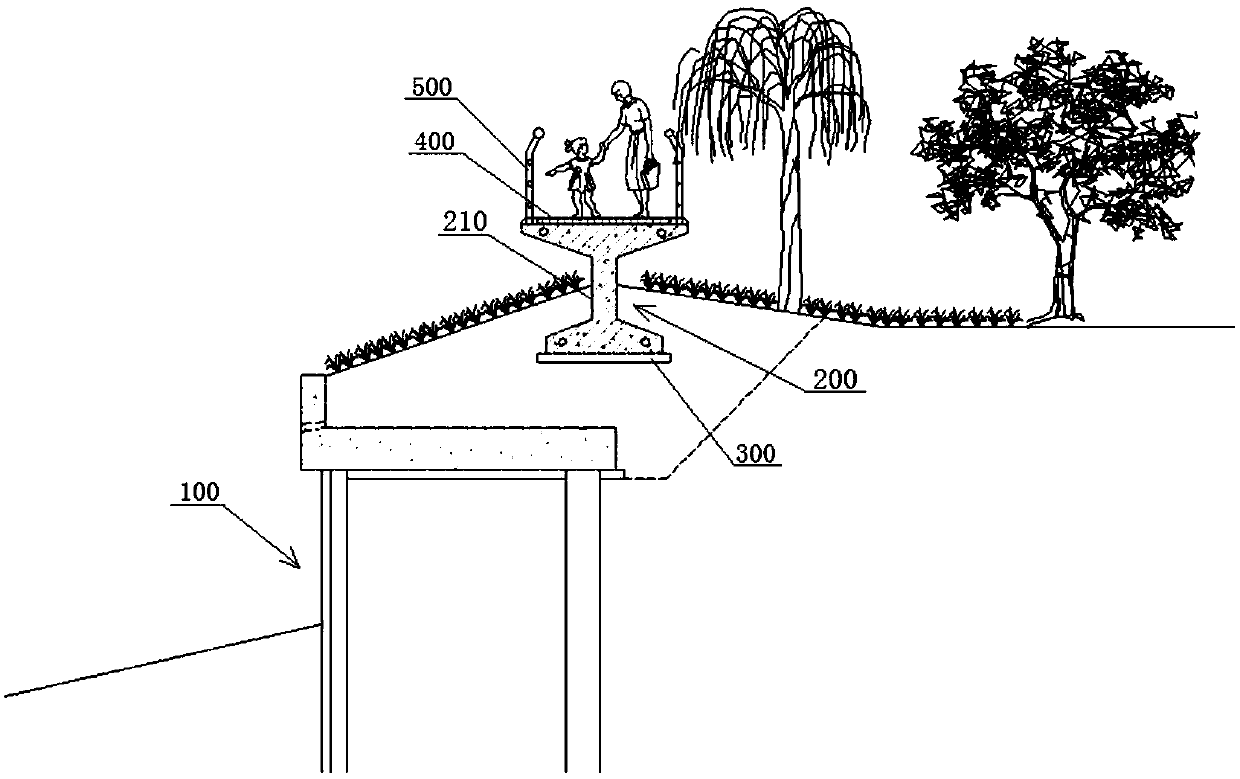
[0034] see figure 1 , shown in the figure is a prefabricated two-stage retaining wall structure, which is set in the revetment section of the river course with high landscape requirements, including the first-level retaining wall 100 set at the river bank and the first-level retaining wall set at the river bank and located at the first level The secondary retaining wall 200 above the retaining wall 100 . The bottom of the secondary retaining wall 200 is provided with a wall cushion 300, and the wall cushion 300 is preferably a plain concrete cushion with a thickness of 100 mm to 200 mm.

[0035] The secondary retaining wall 200 is assembled by several sections of solid wall units 210 along the extension direction of the river bank, and a walkway 400 is built on the top surface of the assembled sections of solid wall units 210, which reduces the slope of the traditional walkway. Occupation, make full use of the river bank space, better river landscape, but also save the overal...

Embodiment 2

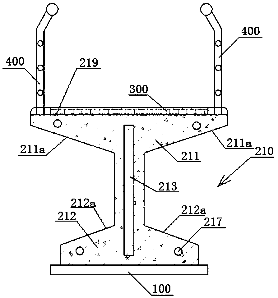
[0044] The structure of this embodiment is roughly the same as that of Embodiment 1, the difference is: see Figure 7 , the solid wall body unit is an inverted T-shaped wall body unit 210', and the inverted T-shaped wall body unit 210' includes a retaining wall bottom plate 211' and a retaining wall body 212', and the retaining wall wall body 212' is vertically arranged on the retaining wall bottom plate 211 ′, on both sides of the retaining wall body 212 ′ on the retaining wall bottom plate 211 ′, a plurality of retaining wall body vertical supports 213 ′ are arranged at intervals along the length direction of the retaining wall bottom plate 211 ′. Wherein, the thickness of the retaining wall bottom plate 211' is 500mm-800mm, the thickness of the retaining wall body 212' is 500mm-800mm, and its height is 1200mm-3000mm. The retaining wall bottom plate 211', the retaining wall body 212' and the retaining wall wall vertical support 213' are integrally formed by concrete prefabri...


PUM

PropertyMeasurementUnit
Lengthaaaaaaaaaa
Lengthaaaaaaaaaa
Widthaaaaaaaaaa

Abstract

The invention discloses a fabricated two-stage retaining wall structure. The fabricated two-stage retaining wall structure comprises a primary retaining wall arranged on a river bank and a secondary retaining wall arranged on the river bank and located above the primary retaining wall, wherein the secondary retaining wall is assembled by a plurality of solid wall body units in the extending direction of the bank line, and a pedestrian way is constructed on the top surfaces of the plurality of solid wall body units after assembly. The secondary retaining wall is assembled by the plurality of solid wall body units and the pedestrian way is constructed on the top surface of the secondary retaining wall, a winding retaining wall line can be created by assembling the solid wall body units withproper length, the problem of singleness of the retaining wall hard structure is solved, and a landscape platform can be formed by increasing width of local wall top.

Description

technical field [0001] The invention relates to the technical field of retaining wall structures, in particular to an assembled two-stage retaining wall structure. Background technique [0002] In river engineering, a retaining wall structure with a certain height needs to be designed according to the engineering level and flood control requirements. Considering the river landscape effect, a two-level retaining wall design scheme is often used in actual projects. The advantage of this design is that the riverside waterfront space landscape Good effect and good hydrophilicity. The traditional two-stage retaining wall structure is to set up a hydrophilic walkway behind the first-level retaining wall, set up a turf slope protection between the walkway and the second-level retaining wall, and set up a pedestrian walkway after the second-level retaining wall. The advantage of this design is that the riverside waterfront space has a good landscape effect and good hydrophilicity. ...

Claims


Application Information

Patent Timeline
IPC IPC(8): E02B3/06E02B3/12E01C9/00E02D29/02
CPCE01C9/00E02B3/066E02B3/12E02D29/0266
Inventor 田利勇鄢亚军
Owner SHANGHAI WATER ENG DESIGN & RES INST
Why Eureka
Try Eureka