Fiber structure and method for changing laser beam profile

A technology of laser beams and optical fibers, applied in the field of laser systems, which can solve the problems of expensive, time-consuming, and damage to fragile optical components of laser systems

Active Publication Date: 2021-11-19
PANASONIC OF NORTH AMERICA
View PDF15 Cites 0 Cited by
  • Summary
  • Abstract
  • Description
  • Claims
  • Application Information

AI Technical Summary

Problems solved by technology

In order to make such changes to the BPP of a laser system, often the output optics or fiber must be swapped and / or realigned with other components, a time-consuming and expensive process that can even lead to damage to fragile optical components of the laser system. unintentional damage

Method used


Image

  • Fiber structure and method for changing laser beam profile
  • Fiber structure and method for changing laser beam profile
  • Fiber structure and method for changing laser beam profile

Examples


Embodiment Construction

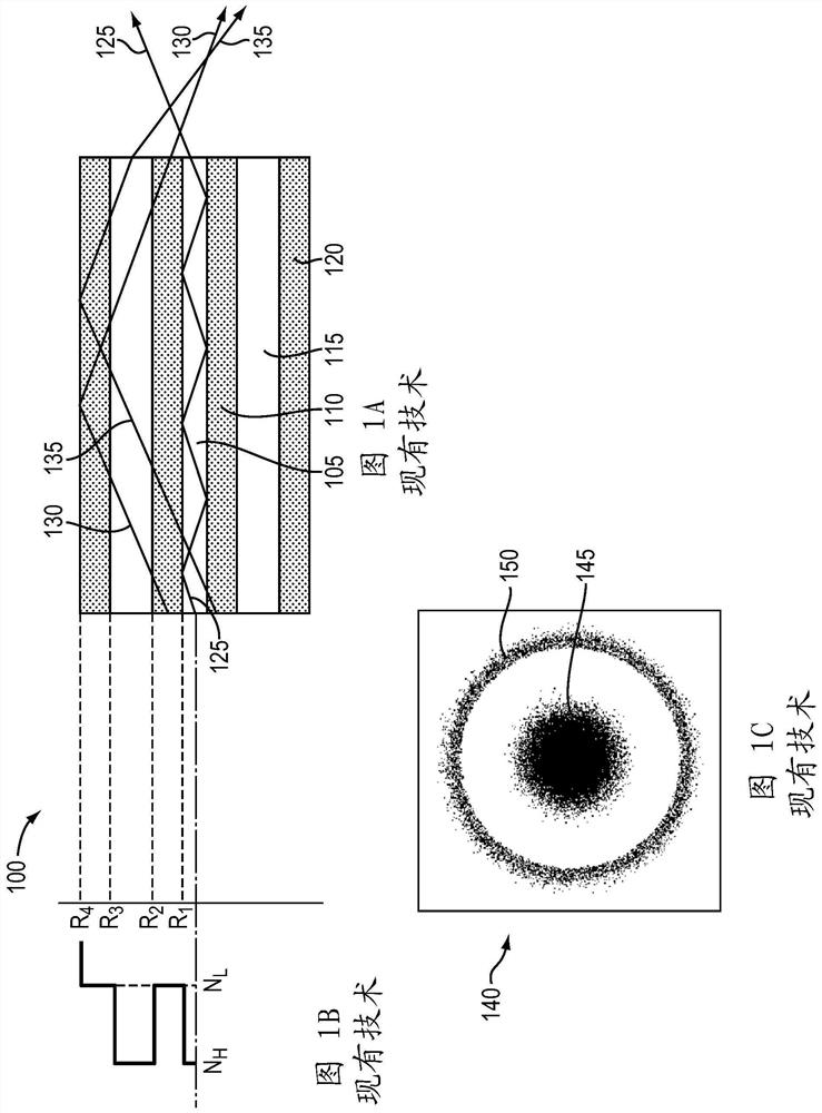
[0034] Figure 1A Shows a conventional double-clad fiber 100, having a central core 105, inner cladding 110, the core 115 and the outer annular layer 120. The radius of each layer (the core or cladding) of the optical fiber 100 by R 1 R 2 R 3 Or R 4 Said that if Figure 1B Indicated. In the conventional double-clad fiber 100, two cores 105, 115 have generally the same high refractive index N H , 110, 120 and the two cladding generally has the same lower refractive index N L ,like Figure 1BShown, therefore, two cores 105, 115 having the same NA: sqrt (N H 2 NN L 2 .

[0035] Figure 1A Also depicts transmission of light of the optical fiber 100 Three. Light 125 is coupled to the central core 105, restricted by the central core 105, and at the same angle it entered the central core 105 emitted from the central core 105. Ray 130 and ray 135 is transmitted to the inner cladding 110, spread over the entire area of ​​the optical fiber, and an outer cladding 120 limit. Since the exit su...


PUM

PropertyMeasurementUnit
thicknessaaaaaaaaaa
thicknessaaaaaaaaaa
diameteraaaaaaaaaa

Abstract

In various embodiments, a stepped-cladding fiber having a central core, a first cladding, a ring core, and a second cladding is utilized to tune the beam parameter product and / or numerical aperture of the laser beam.

Description

[0001] Application [0002] This application claims the benefit of US Provisional Patent April 6, 2016, filed benefit and priority No.62 / 318,959, the entire disclosure of which is incorporated herein by reference. Technical field [0003] In various embodiments, the present invention relates to a laser system, in particular having a controllable beam profile (e.g., a variable beam parameter product) of the laser system. Background technique [0004] High power laser systems used in many different applications, such as welding, cutting, drilling, and material processing. Such laser systems typically include a laser emitter, which is coupled to the laser light from the optical fiber (or simply "fibers"), laser light from the optical fiber and the focusing optical system on the workpiece to be machined. The optical system is typically designed to produce the highest quality of a laser beam, or, equivalently, with the lowest beam parameter product (the BPP) beam. BPP is the product...

Claims


Application Information

Patent Timeline
Patent Type & Authority Patents(China)
IPC IPC(8): G02B6/036
CPCH01S5/0071H01S5/143H01S5/4031H01S5/405H01S5/4062H01S5/4087H01S2301/20G02B6/4214G02B2006/12104G02B2006/12121G02B6/03644H01S5/005G02B6/32G02B6/02042G02B6/34G02B17/00
Inventor 周望龙F·维拉里尔-绍塞多P·塔耶巴提B·陈
Owner PANASONIC OF NORTH AMERICA
Why Eureka
Try Eureka