Infusion hand fixing device

A fixation device and hand technology, applied in the direction of hypodermic injection equipment, etc., can solve problems such as soreness or numbness, patient discomfort, and weak hand fixation effect, and achieve the effect of preventing hand movement

Inactive Publication Date: 2018-11-16
邱庚荣
View PDF6 Cites 8 Cited by
  • Summary
  • Abstract
  • Description
  • Claims
  • Application Information

AI Technical Summary

Problems solved by technology

At present, the infusion prevents the hand from moving by pressing the hand, which is mandatory, and the effect of immobilizing the hand is not strong; when the infusion time is too long, if the hand does not move for a long time, it is easy to feel sore or numb, which makes the patient feel uncomfortable

Method used


Image

  • Infusion hand fixing device
  • Infusion hand fixing device

Examples


Embodiment 1

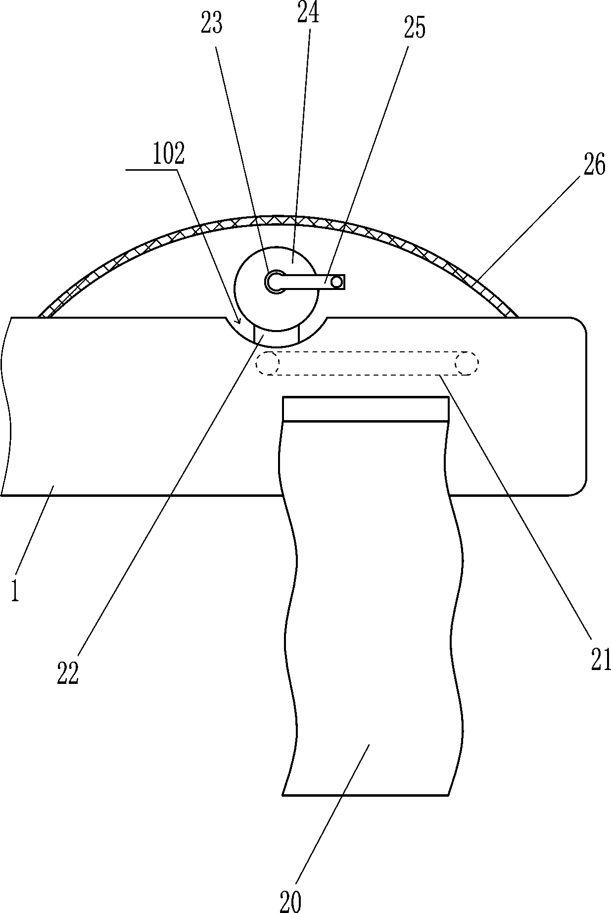
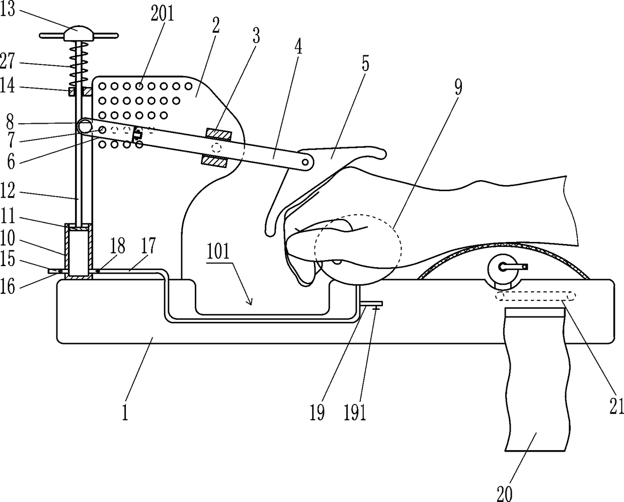
[0014] A hand fixation device for infusion, such as Figure 1-2 As shown, it includes a supporting plate 1, a mounting plate 2, a sliding sleeve 3, a sliding rod 4, a pressing plate 5, a connecting rod 6, a clamping column 7, a handle 8, an air bag 9, a cylinder body 10, a piston 11, a pull rod 12, and a handle 13. Orifice plate 14, suction pipe 15, suction valve 16, air outlet pipe 17, air outlet valve 18, air release pipe 19, air release valve 191 and spring 27, a rectangular groove 101 is opened on the left side of the top of the supporting plate 1, and the support The top left side of the plate 1 is connected with the mounting plate 2, the mounting plate 2 is located on the left side of the rectangular groove 101, the upper left side of the front side of the mounting plate 2 has a plurality of round holes 201, and the top left side of the supporting plate 1 is connected with the cylinder body 10, The cylinder body 10 is located on the left side of the mounting plate 2, and...

Embodiment 2

[0016] A hand fixation device for infusion, such as Figure 1-2 As shown, it includes a supporting plate 1, a mounting plate 2, a sliding sleeve 3, a sliding rod 4, a pressing plate 5, a connecting rod 6, a clamping column 7, a handle 8, an air bag 9, a cylinder body 10, a piston 11, a pull rod 12, and a handle 13. Orifice plate 14, suction pipe 15, suction valve 16, air outlet pipe 17, air outlet valve 18, air release pipe 19, air release valve 191 and spring 27, a rectangular groove 101 is opened on the left side of the top of the supporting plate 1, and the support The top left side of the plate 1 is connected with the mounting plate 2, the mounting plate 2 is located on the left side of the rectangular groove 101, the upper left side of the front side of the mounting plate 2 has a plurality of round holes 201, and the top left side of the supporting plate 1 is connected with the cylinder body 10, The cylinder body 10 is located on the left side of the mounting plate 2, and...


PUM


Abstract

The invention relates to a fixing device, and in particular to an infusion hand fixing device. The invention aims at solving a technical problem of providing the infusion hand fixing device, which iscapable of fixing a hand and relieving sourness and numbness of the hand. According to the technical scheme, the infusion hand fixing device comprises a supporting plate, a mounting plate, a sliding sleeve, a sliding rod, a pressing plate, a connecting rod, a clamping pillar, a handle, an airbag, a cylinder body, a piston and the like, wherein a rectangular groove is formed in the left side of thetop of the supporting plate; the mounting plate is connected to the left side of the top of the supporting plate; the mounting plate is arranged at the left side of the rectangular groove; a plurality of round holes are formed in the left side of the upper part of the front side face of the mounting plate; the cylinder body is connected to the left side of the top of the supporting plate; the cylinder body is arranged at the left side of the mounting plate; and the piston is movably arranged in the cylinder body. According to the fixing device provided by the invention, the sliding rod is rotated by medical personnel so as to drive the pressing plate to rotate; the position of the pressing plate can be adjusted in accordance with a hand of a patient, and the hand back of the patient can be fixed; and by continuously the pull rod up and down through pulling, external air can enter the cylinder body, so that the airbag can be continuously inflated.

Description

technical field [0001] The invention relates to a fixing device, in particular to a hand fixing device for transfusion. Background technique [0002] When people are sick, they are often treated with drugs. Some drugs are not suitable for oral administration, and are often more suitable for direct infusion, and the efficacy of the drug is reflected through infusion. During the infusion, if the hand is moved randomly, the needle will easily come out, the blood will flow back, and cause swelling. Only by not moving the hand can ensure that the medicine can completely enter the muscle tissue. At present, to prevent hand movement during infusion, it is generally to press and hold the hand, which is mandatory, and the effect of immobilizing the hand is not strong; when the infusion time is too long, the hand will easily become sore or numb if it has not been moved, which will make the patient feel uncomfortable. Contents of the invention [0003] In order to overcome the disad...

Claims


Application Information

Patent Timeline
Patent Type & Authority Applications(China)
IPC IPC(8): A61M5/52
CPCA61M5/52
Inventor 邱庚荣
Owner 邱庚荣
Why Eureka
Try Eureka