Valve protecting box for irrigation

A technology for protecting boxes and valves, which is applied in valve details, valve devices, valve shell structures, etc., to facilitate disassembly and post-maintenance, improve sealing effect, and improve sealing performance.

Pending Publication Date: 2018-11-16
FARMLAND IRRIGATION RES INST CHINESE ACAD OF AGRI SCI
View PDF8 Cites 0 Cited by
  • Summary
  • Abstract
  • Description
  • Claims
  • Application Information

AI Technical Summary

Problems solved by technology

[0005] The invention provides a valve protection box for irrigation, the valve protection box adopts a double-box design, and the pipe hole is open, which solves the problems of convenient disassembly and later maintenance, and improves the sealing effect

Method used


Image

  • Valve protecting box for irrigation
  • Valve protecting box for irrigation
  • Valve protecting box for irrigation

Examples


Embodiment 1

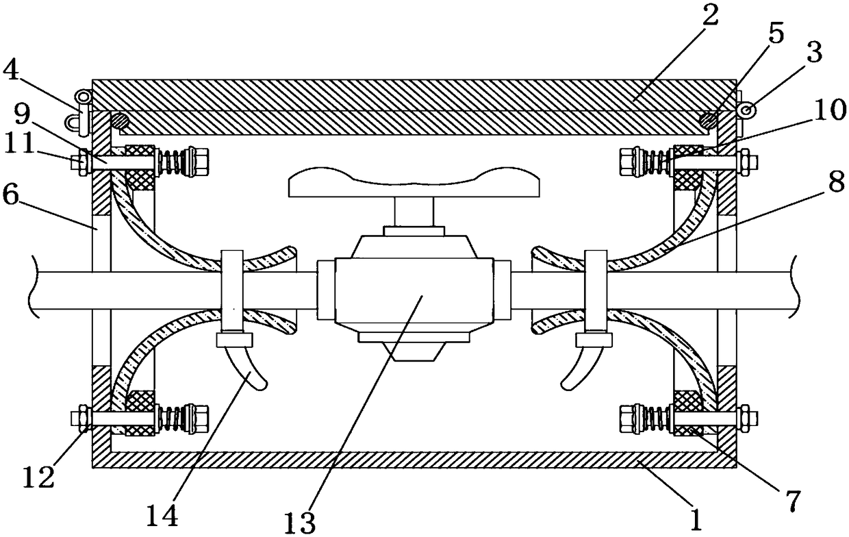
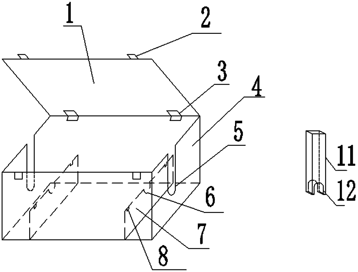
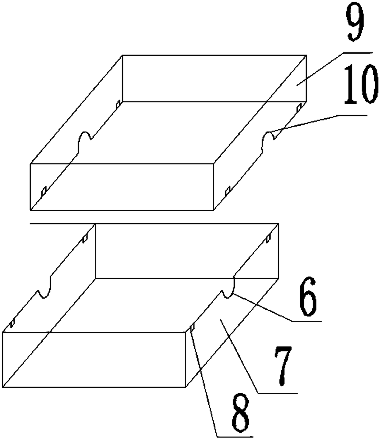
[0031] as attached Figure 2-3 As shown, a valve protection box for irrigation, the valve protection box includes an outer box cover plate 1, an outer box buckle 2, an outer box hinge 3, an outer box body 4, and a lower half of the outer box through a pipe hole 5 , inner box lower half piercing hole 6, inner box lower box body 7, inner box hasp 8, inner box upper box body 9, inner box upper half piercing hole 10, outer box piercing hole clip 11, outer box Upper half pipe hole 12;

[0032] The outer box cover plate 1 is connected with the outer box box body 4 through the outer box hinge 3; the outer box hinge 3 has two ends arranged on the outer box box body 4; the outer box hasp 2 has two One is arranged on the opposite end of the outer box hinge 3; the lower half of the outer box piercing hole 5 is arranged on the two ends of the outer box body 4; the lower half of the inner box piercing hole 6 is arranged on the left and right sides of the inner box lower box body 7 two en...

Embodiment 2

[0043] as attached Figure 2-3 As shown, a valve protection box for irrigation, the valve protection box includes an outer box cover plate 1, an outer box buckle 2, an outer box hinge 3, an outer box body 4, and a lower half of the outer box through a pipe hole 5 , inner box lower half piercing hole 6, inner box lower box body 7, inner box hasp 8, inner box upper box body 9, inner box upper half piercing hole 10, outer box piercing hole clip 11, outer box Upper half pierces pipe hole 12.

[0044] The outer box cover plate 1 is connected with the outer box box body 4 through the outer box hinge 3; the outer box hinge 3 has two ends arranged on the outer box box body 4; the outer box hasp 2 has two One is arranged on the opposite end of the outer box hinge 3; the lower half of the outer box piercing hole 5 is arranged on the two ends of the outer box body 4; the lower half of the inner box piercing hole 6 is arranged on the left and right sides of the inner box lower box body 7...


PUM


Abstract

The invention discloses a valve protecting box for irrigation. The valve protecting box for irrigation comprises an outer box cover plate, an outer box hasp, an outer box hinge, an outer box body, outer box lower half pipe penetrating holes, an inner box lower half pipe penetrating hole, an inner box lower body, an inner box hasp, an inner box upper body, inner box upper half pipe penetrating holes, outer box pipe penetrating hole clamping plates and an outer box upper half pipe penetrating hole; the outer box cover plate is connected with the outer box body through the outer box hinge; the outer box lower half pipe penetrating holes are formed in the two ends of the outer box body; the inner box lower half pipe penetrating holes are formed in the left and right ends of the inner box lowerbody; the inner box upper body and the inner box lower body are arranged in the outer box body; the inner box upper half pipe penetrating holes are formed in the left and right ends of the inner boxupper body; two outer box pipe penetrating hole clamping plates are provided; the outer box pipe penetrating hole clamping plates and the outer box lower half pipe penetrating holes are in inserted connection; as the outer box cover plate and the inner box upper body can be totally opened, the disassembly and later maintenance of valves and instruments are convenient; and in addition, the double-box design is adopted, so that the tightness is improved.

Description

technical field [0001] The invention relates to the technical field of irrigation test plots, in particular to a valve protection box for irrigation. Background technique [0002] The valve protection box is a kind of valve protection device, which has the characteristics of beauty, durability, and easy installation; the existing valve protection box has fewer devices to protect, mainly the valves in farmland and garden irrigation, and urban water supply and drainage projects. In the irrigation experiment area or the greenhouse experiment area, there are not only valves, but also precision instruments such as control devices, metering devices, and pressure display devices, so stricter requirements are placed on the sealing. In addition, the irrigation experiment area or the greenhouse test area site Limited, the valve protection box needs to be placed underground, and the cover plate of the valve protection box is flush with the ground level, so it is required to facilitate ...

Claims


Application Information

Patent Timeline
Patent Type & Authority Applications(China)
IPC IPC(8): F16K27/12F16J15/10
CPCF16J15/10F16K27/12
Inventor 孙浩黄修桥韩启彪范永申陈震孙秀路刘杨
Owner FARMLAND IRRIGATION RES INST CHINESE ACAD OF AGRI SCI
Why Eureka
Try Eureka