Radar position control device for unmanned vehicle and method

An unmanned vehicle and radar position technology, applied in the field of unmanned vehicle radar position control devices, can solve problems such as hidden dangers of unmanned vehicles, inability to perceive real-time road conditions behind the vehicle, etc., and achieves strong popularization, simple structure, and easy installation. Effect

Inactive Publication Date: 2018-11-30
WUHAN UNIV OF TECH
View PDF7 Cites 1 Cited by
  • Summary
  • Abstract
  • Description
  • Claims
  • Application Information

AI Technical Summary

Problems solved by technology

However, the current radar installation method is generally fixed-point installation in front of the vehicle. The disadvantage of this installation method on engineering vehicles is that it cannot perceive the real-time road conditions behind the vehicle, so there will be great hidden dangers in unmanned driving.

Method used


Image

  • Radar position control device for unmanned vehicle and method

Examples


Embodiment Construction

[0010] In order to better understand the present invention, the following further describes the present invention with reference to the accompanying drawings and embodiments.

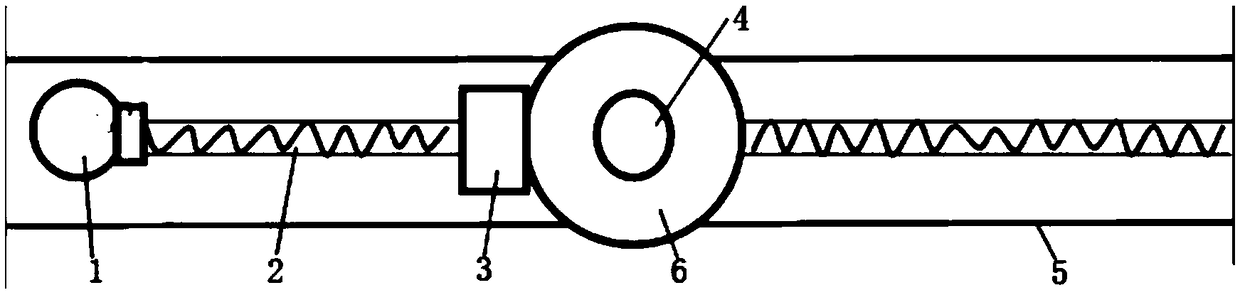
[0011] Such as figure 1 As shown, an unmanned vehicle radar position control device includes a base 5, a translation motor 1, a lead screw 2, a lead screw nut 3, a radar assembly and a control system. The base is set on the unmanned vehicle, and the translation motor is located One end of the base, one end of the lead screw is connected to the output shaft of the translation motor, the other end of the lead screw is fixed on the base through a bearing, and the lead screw nut is connected to the lead screw configuration. The radar assembly includes the radar body 6, the connecting base 4 and the rotating motor. The connecting seat is connected with the screw nut, the rotating motor is arranged on the connecting seat, the output shaft of the rotating motor is connected with the radar body, and the control sy...


PUM


Abstract

The invention provides a radar position control device for an unmanned vehicle and a method. The radar position control device for the unmanned vehicle comprise a base, a translation motor, a lead screw, a lead screw nut, a radar assembly and a control system, wherein the base is arranged on the unmanned vehicle, the translation motor is arranged at one end of the base, one end of the lead screw is connected with an output shaft of the translation motor; the other end of the lead screw is fixed to the base through a bearing, the lead screw nut is connected with the lead screw in a configuration mode, the radar assembly comprises a radar body, a connecting seat and a rotating motor, the connecting seat is connected with the lead screw nut, the rotating motor is arranged on the connecting seat, an output shaft of the rotating motor is connected with the radar body, and the control system controls the starting, stopping and steering of the translation motor and the rotating motor. The radar position control device for the unmanned vehicle realizes the real-time detection of the front and rear road conditions by the radar, greatly improves the driving safety and stability, has simple structure, is convenient to install, and has high popularization.

Description

Technical field [0001] The invention belongs to the technical field of unmanned vehicles, and in particular relates to an unmanned vehicle radar position control device and method. Background technique [0002] At present, the environmental perception technology in the field of unmanned driving mainly provides environmental information to subsequent technical modules by processing data collected by sensors equipped on smart cars such as vision and radar. The environmental perception system is a key factor in the level of intelligence of unmanned vehicles. However, the current radar installation method is generally fixed at the front of the vehicle. The disadvantage of this installation method on the engineering vehicle is that it cannot perceive the real-time road conditions behind the vehicle, so unmanned driving will have great hidden dangers. Installing two radars at the same time to separately collect front and rear data will greatly increase the cost. The present invention ...

Claims


Application Information

Patent Timeline
Patent Type & Authority Applications(China)
IPC IPC(8): G05D3/20
CPCG05D3/20
Inventor 颜伏伍肖振明卢炽华华林许垒龙
Owner WUHAN UNIV OF TECH
Why Eureka
Try Eureka