Clamping device

A clamping device and pallet technology, applied in workpiece clamping devices, manufacturing tools, etc., can solve the problems of limited cylinder stroke and only applicable

Pending Publication Date: 2020-04-21
苏州托克斯冲压设备有限公司
View PDF0 Cites 0 Cited by
  • Summary
  • Abstract
  • Description
  • Claims
  • Application Information

AI Technical Summary

Problems solved by technology

[0002] The traditional clamping tool mainly has the following problems: when the workpiece is assembled or stamped, the ordinary clamping tool usually uses the cylinder to drive the linkage mechanism to clamp and position the workpiece when the workpiece is clamped and opened. The stroke of the cylinder is limited, and the connecting rod mechanism can only rotate a small angle, that is, it can only be applied to occasions where the workpiece size is small

Method used


Image

  • Clamping device
  • Clamping device
  • Clamping device

Examples


Embodiment Construction

[0021] The preferred embodiments of the present invention will be described in detail below in conjunction with the accompanying drawings, so that the advantages and features of the present invention can be more easily understood by those skilled in the art, so as to define the protection scope of the present invention more clearly.

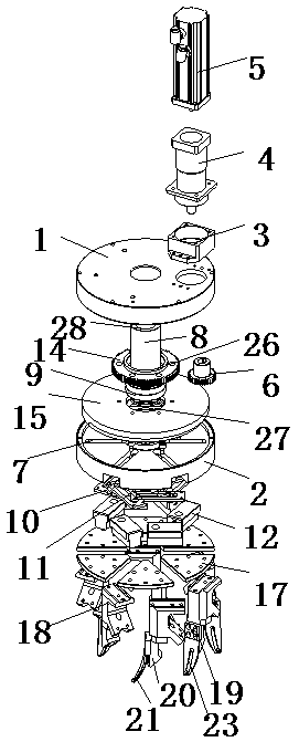
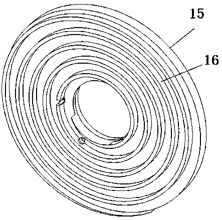
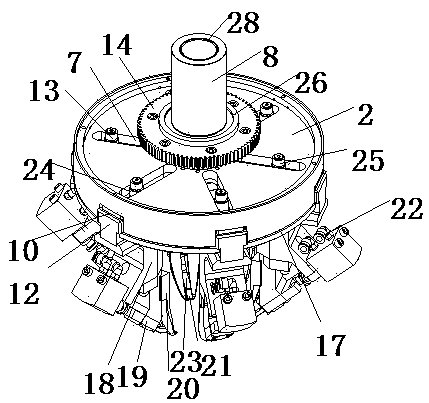
[0022] See attached figure 1 To attach Image 6 , with figure 1 It is a three-dimensional disassembled view of the clamping device according to the present invention, with figure 2 It is a perspective view of the spiral rotating disc of the clamping device according to the present invention, with image 3 It is a perspective view of the expanded state of the spiral rotating disc according to the present invention, with Figure 4 It is a perspective view of the clamped state of the spiral rotating disk according to the present invention, with Figure 5 It is a top view of the expanded state of the spiral rotating disk according to the present...


PUM


Abstract

The invention discloses a multi-angle and large-stroke clamping device. The device comprises an adapter plate and a tray; a servo motor and a driving gear are arranged on the adapter plate; a plurality of guide grooves are distributed in the tray in the radius direction; a main shaft is longitudinally arranged in the center of the tray; after the main shaft penetrates through the tray, a stop sleeve is connected below the tray; a plurality of sliding plates are arranged on the stop sleeve in a central symmetry manner; each sliding plate is provided with a sliding groove corresponding to a corresponding guide groove; sliding blocks are arranged below the sliding plates; a rotor is arranged above the sliding blocks; a driven gear in transmission connection with the driving gear is rotatablyarranged on the main shaft; the driving gear and the driven gear are positioned between the adapter plate and the tray; a spiral rotating disc is fixedly arranged below the driven gear; the spiral rotating disc is located above the tray, a spiral groove is formed in a lower surface of the spiral rotating disc, the rotor penetrates through the guide grooves to be installed in the spiral groove, a plurality of pressing plates are connected to a lower portion of the tray, the sliding blocks can be movably arranged between adjacent pressing plates along the radius, and a clamping component is connected to a lower portion of each sliding block.

Description

technical field [0001] The invention relates to a clamping device. Background technique [0002] The traditional clamping tool mainly has the following problems: when the workpiece is assembled or stamped, the ordinary clamping tool usually uses the cylinder to drive the linkage mechanism to clamp and position the workpiece when the workpiece is clamped and opened. The stroke of the cylinder is limited, and the connecting rod mechanism can only rotate a small angle, that is, it can only be applied to occasions where the workpiece size is small. Contents of the invention [0003] In order to overcome the problems in the prior art, the purpose of the present invention is to provide a multi-angle, large-stroke clamping device. [0004] In order to achieve the above object, the present invention provides a clamping device, including a transfer disc and a tray combined in the longitudinal direction, the transfer disc is provided with a motor base, a servo motor, a reducer, and...

Claims


Application Information

Patent Timeline
Patent Type & Authority Applications(China)
IPC IPC(8): B25B11/02
CPCB25B11/02
Inventor 郭辉任永祝陶筱天
Owner 苏州托克斯冲压设备有限公司
Why Eureka
Try Eureka