

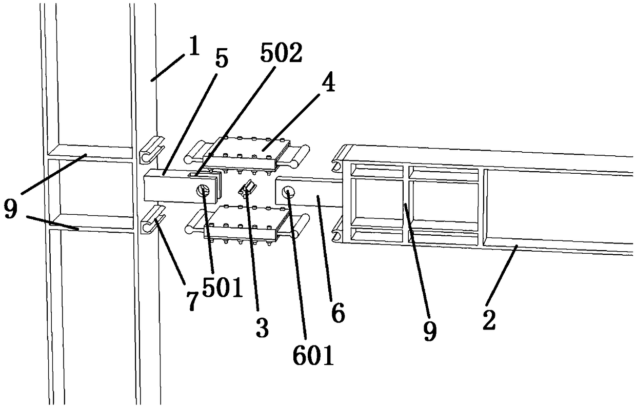
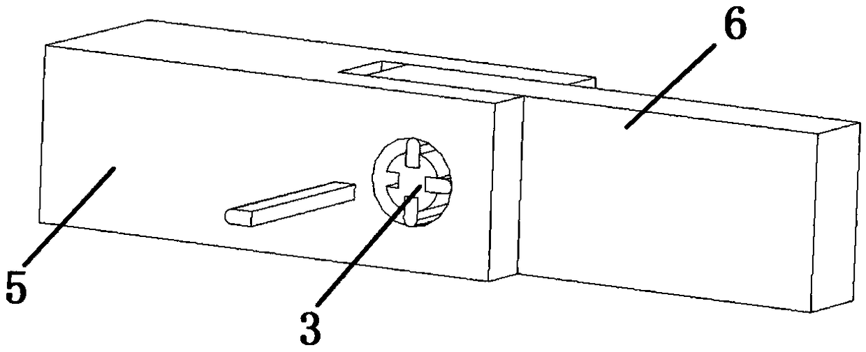
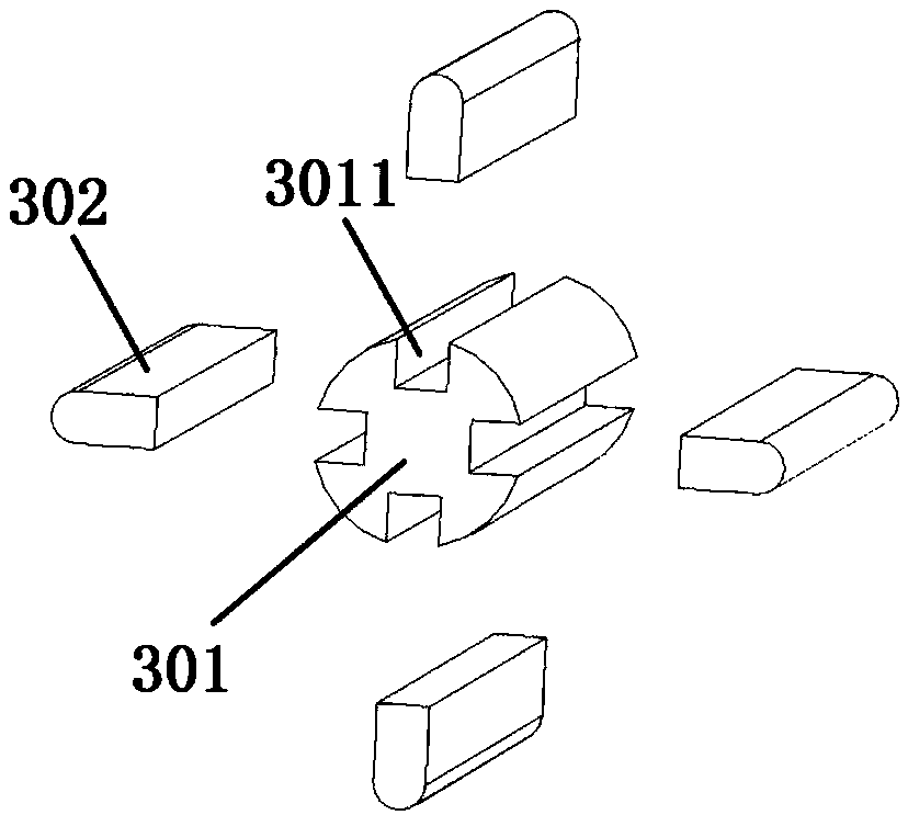
Beam column connection node
A beam-column connection and node technology, applied in the direction of building types, buildings, building components, etc., can solve problems such as high processing and construction precision requirements, increased construction procedures, high reinforcement costs, etc., to facilitate construction operations and reduce serious structural losses , The effect of fast and efficient installation
- Summary
- Abstract
- Description
- Claims
- Application Information
AI Technical Summary
Problems solved by technology
Method used
Image

Examples
Embodiment Construction
[0026] In the description of the present invention, it should be noted that the terms "center", "longitudinal", "transverse", "upper", "lower", "front", "rear", "left", "right", " The orientations or positional relationships indicated by "vertical", "horizontal", "top", "bottom", "inner", "outer", etc. are based on the orientation or positional relationship shown in the drawings, and are only for the convenience of describing the present invention and simplifying Describes, but does not indicate or imply that the device or element referred to must have a specific orientation, be constructed in a specific orientation, and operate in a specific orientation, and therefore should not be construed as limiting the present invention. In addition, the terms "first", "second", and "third" are used for descriptive purposes only, and should not be construed as indicating or implying relative importance.
[0027] In the description of the present invention, it should be noted that unless ...
PUM
 Abstract
Description
Claims
Application Information