A combined bidirectional DC-DC conversion circuit

A bidirectional DC conversion and combined technology, applied in the field of DC non-isolated conversion devices, can solve the problems of increased winding difficulty and increased loss, and achieve the effect of simple control scheme, easy implementation and high efficiency

Inactive Publication Date: 2018-12-25
IANGSU COLLEGE OF ENG & TECH
View PDF4 Cites 6 Cited by
  • Summary
  • Abstract
  • Description
  • Claims
  • Application Information

AI Technical Summary

Problems solved by technology

Although it uses the coupled inductance to avoid the defects caused by the body diode of the switch tube, it brings: during each turn-on and turn-off process of the switch tube, due to the resonance of the coupled inductor and the internal circulation of the coupled inductor, the The problem of causing additional loss; at the same time, the coupled inductance also increases the difficulty of winding

Method used


Image

  • A combined bidirectional DC-DC conversion circuit
  • A combined bidirectional DC-DC conversion circuit
  • A combined bidirectional DC-DC conversion circuit

Examples


Embodiment 1

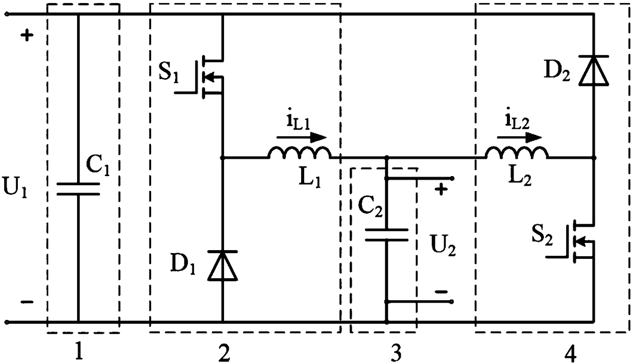
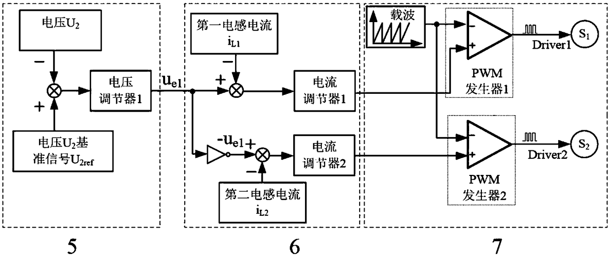
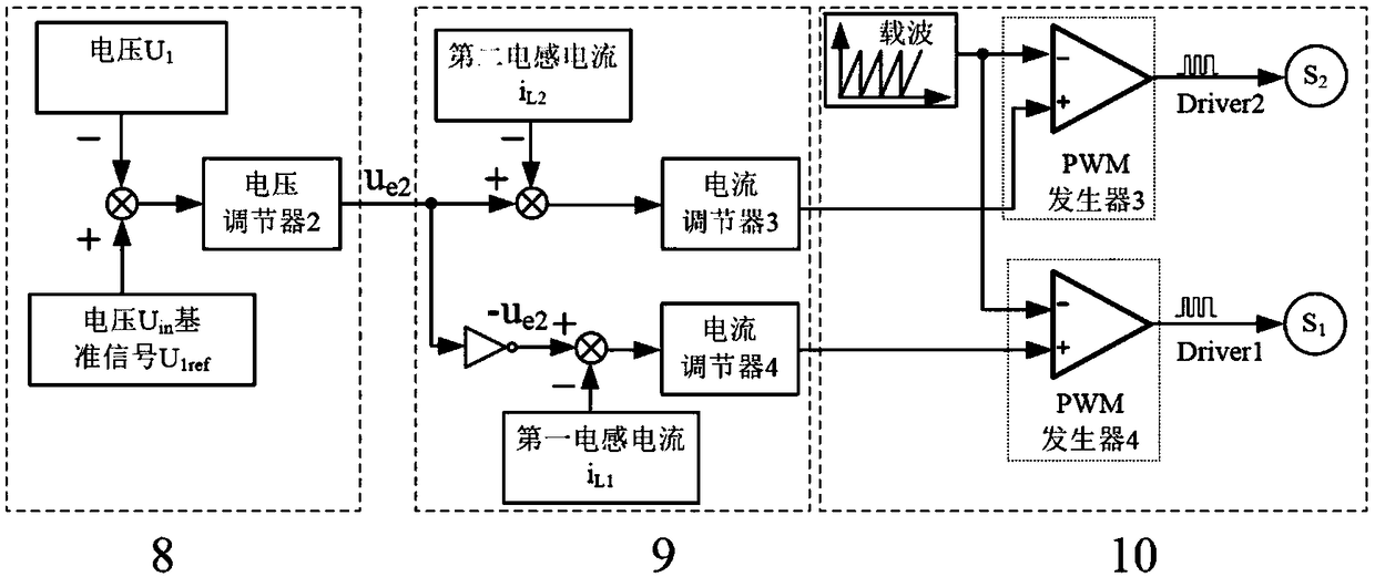
[0043] refer to Figure 1-3 , a combined bidirectional DC conversion circuit and its control method, which includes a first-end filter capacitor 1, a step-down bridge arm circuit 2, a second-end filter capacitor 3, a boost bridge arm circuit 4, a first total voltage Ring controller 5, the first total current loop controller 6, the first total PWM generator 7, the second total voltage loop controller 8, the second total current loop controller 9, the second total PWM generator 10; the first The terminal filter capacitor 1 includes: the first terminal filter capacitor C 1 , where the first power switch S 1 The drain of the second freewheeling diode D 2 The cathode of the two is connected, and the first end of the filter capacitor C is connected to the connector of the two 1 One end of the first freewheeling diode D 1 The anode of the second power switch tube S 2 The source is connected, and the first end of the filter capacitor C is connected to the connector of the two 1 ...

Embodiment 2

[0045] Referring to FIGS. 4-5 , the working principle of the combined bidirectional DC conversion circuit and its control method described in Embodiment 1 is divided into two parts. The breakdown is as follows:

[0046] 1. The working part of the step-down bridge arm circuit

[0047] When power is needed from the first terminal filter capacitor C 1 End to second end filter capacitor C 2 end, when it flows, the step-down bridge arm circuit 2 works, and the step-up bridge arm circuit 4 does not work, and the electric energy is transferred to the filter capacitor C at the second end through the first inductance L1 2 end delivery. This part of the circuit has two working modes:

[0048] 1. Working mode I

[0049] As shown in Figure 4(a), the first switching tube S 1 conduction, the first terminal filter capacitor C 1 terminal power to the second terminal filter capacitor C 2 end delivery, the first freewheeling diode D 1 , the second power switch tube S 2 , the second fr...

Embodiment 3

[0059] refer to Figure 6-13 . The main simulation experiments are done with a combined bidirectional DC conversion circuit and its control method described in Embodiment 1 and Embodiment 2.

[0060] The simulation parameters are as follows: the switching frequency is 50kHz, the first inductor L 1 inductance and the second inductance L 2 The inductance is 100μH, the filter capacitor C at the first end 1 and the second terminal filter capacitor C 2 They are 1000μF, and the load R is a 2Ω resistive load.

[0061] Figure 8 , Figure 9 and Figure 10 given by the second terminal filter capacitor C 2 Terminal voltage U 2 Some main simulation waveforms of the example of the present invention when it is the control object. The first end filter capacitor C 1 Terminal voltage U 1 is a 48V voltage source, the second terminal filter capacitor C 2 Terminal voltage U2 is controlled at 24V.

[0062] From Figure 8 , Figure 10 It can be seen that: when the injected current ...


PUM


Abstract

The invention discloses a combined bidirectional DC-DC conversion circuit, belonging to an energy bi-directional flow DC-DC conversion technology. When energy is required to flow from a filter capacitor end of a first terminal to a filter capacitor end of a second terminal, the invention can automatically realize the operation of a step-down bridge arm circuit, and the step-up bridge arm circuit does not work. When energy is required to flow from the filter capacitor terminal of the second terminal to the filter capacitor terminal of the first terminal, the invention can automatically realizethe operation of the boost bridge arm circuit, and the buck bridge arm circuit is not operated. As two inductors are serially connected between the step-down bridge arm circuit and the step-up bridgearm circuit, the problem that two power switch transistors in the two bridge arm circuits are directly connected does not exist, and the reliability of the conversion circuit is greatly improved. At the same time, the use of independent diodes as freewheeling diodes is conducive to optimizing the design of power devices and improving the efficiency of the converter. The present invention is suitable for electric vehicles, fuel cells, photovoltaic power generation, wind power generation and other new energy supply systems requiring bidirectional energy flow.

Description

technical field [0001] The invention relates to a direct current non-isolated conversion device in a power conversion device, more specifically, it relates to a direct current power bidirectional flow converter. Background technique [0002] In order to reduce the volume and weight of the system and save costs, bidirectional DC conversion circuits have been used more and more widely in applications such as battery charging and discharging, electric vehicles, UPS systems, new energy power generation systems, and micro DC grids. The direction of the input and output currents of the bidirectional DC converter can be changed, which is equivalent to two unidirectional DC converters in terms of power transmission. research value. [0003] At present, non-isolated half-bridge bidirectional DC conversion circuits have been widely used. However, since the straight-through problem of the switching tube affects its reliability, and the freewheeling diode is the body diode of the swit...

Claims


Application Information

Patent Timeline
IPC IPC(8): H02M3/158
CPCH02M3/158H02M1/0058Y02E10/56Y02E10/76
Inventor 张先进范才红朱海荣宋永献
Owner IANGSU COLLEGE OF ENG & TECH
Why Eureka
Try Eureka