Network cable tester

A tester and network cable technology, applied in the field of network maintenance equipment, can solve the problems of slow test speed, difficult judgment and high professional requirements

Inactive Publication Date: 2019-01-04
WEIFANG UNIVERSITY
View PDF0 Cites 2 Cited by
  • Summary
  • Abstract
  • Description
  • Claims
  • Application Information

AI Technical Summary

Problems solved by technology

[0004] (1) The test speed is slow: During the test process, the continuity and line sequence of the network cable need to be displayed in sequence. It takes about 5 to 10 seconds to test the continuity of a network cable, which takes a long time;
[0005] (2) The professional requirements for judging the accuracy of the line sequence are relatively high. For non-professionals, it is difficult to make an accurate judgment, especially for the judgment of whether the line sequence of the precursor line and the cross line is correct.

Method used


Image

  • Network cable tester
  • Network cable tester
  • Network cable tester

Examples


Embodiment 1

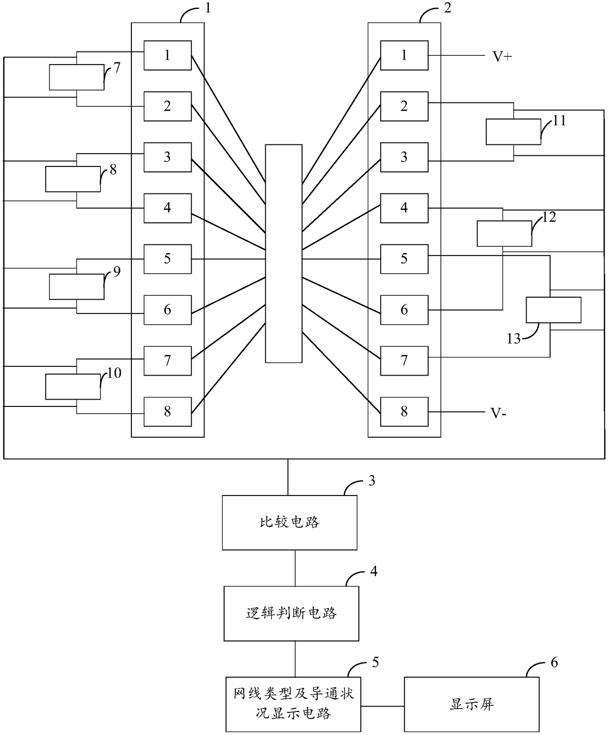
[0055] figure 1 A structural block diagram of the network cable tester provided by the present invention is shown, and for the convenience of description, only the parts related to the embodiment of the present invention are shown in the figure.

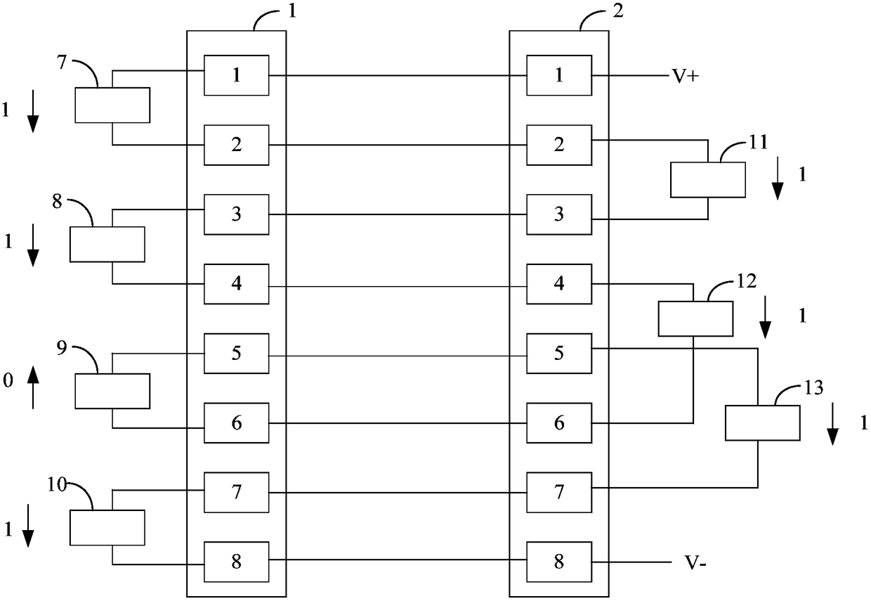
[0056] The network cable tester includes a first network cable socket 1 and a second network cable socket 2. The first network cable socket 1 and the second network cable socket 2 are respectively connected to the two crystal heads of the network cable to be tested. The first network cable socket 1 and the second network cable socket 2 are provided with pin 1, pin 2, pin 3, pin 4, pin 5, pin 6, pin 7 and pin 8;

[0057] The first network cable socket 1 is provided with four impedance circuits, and the second network cable socket 2 is provided with three impedance circuits;

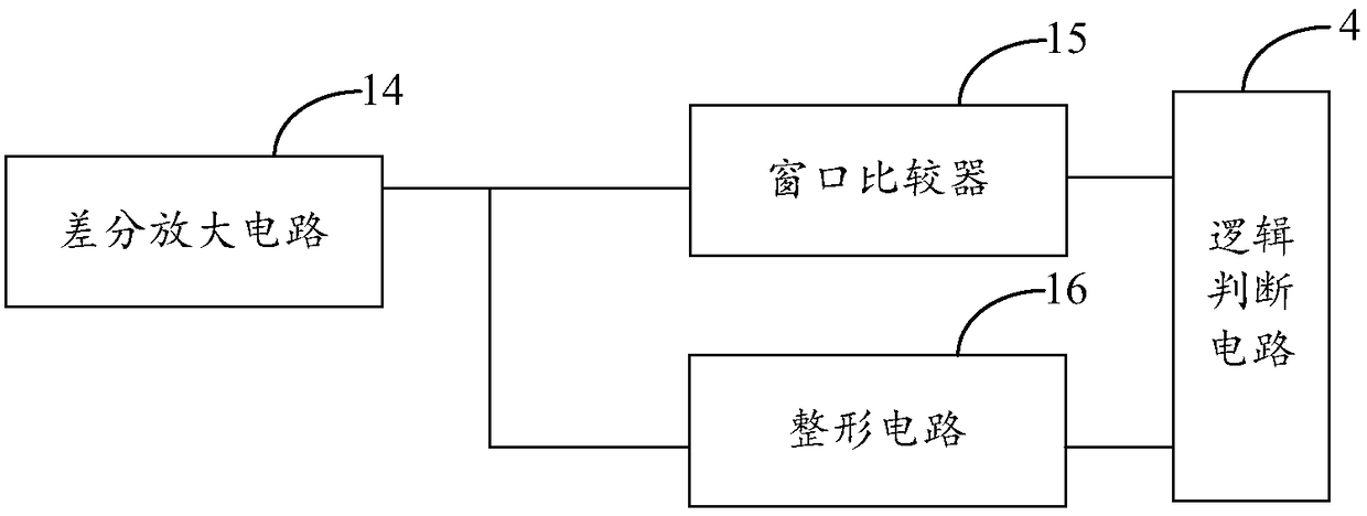
[0058] The output terminals of the seven impedance circuits are all connected to the comparison circuit 3, and the comparison circuit 3 is used to shape and con...

Embodiment 2

[0086] In the embodiment of the present invention, on the basis of the first embodiment, the network cable tester further includes a coded signal conduction test unit;

[0087] The coded signal conduction test unit is used to detect and test the signal transmission quality of the network cable to be tested;

[0088] Such as Figure 6 As shown, the coded signal conduction test unit includes a coded signal generating module 17, a coded signal receiving module 18, a coded signal judging module 19 and a coded signal display module 20;

[0089] The encoding signal generating module 17 corresponds to pin 1, pin 2, pin 3, pin 4, pin 5, pin 6, pin 7 and pin 8 of the first network cable socket 1 respectively The connection is used to generate time-division interleaved coded signals of a 100-megabit rate and a gigabit-rate, the coded signals of a 100-megabit rate and the coded signals of a gigabit rate contain different identification codes, and the generated coded signals are transmit...

Embodiment 3

[0096] Such as Figure 7 As shown, on the basis of Embodiment 2, the network cable tester also includes a network cable conduction single-ended test unit;

[0097] The network cable conduction single-ended test unit includes an alternating magnetic field generation module 27, an amplification and rectification circuit 21, a logic judgment module 22, and a single-ended conduction state display module 23;

[0098] Such as Figure 8 As shown, the alternating magnetic field generation module 27 includes an oscillating circuit 24, a coil 25 and a clamp iron core 26, the output of the oscillation circuit 24 is connected to the coil 25, and the coil 25 is wound on the clamp iron core 26 Above, the clamp iron core 26 is provided with a notch, the notch is used to place the network cable to be tested, and the alternating magnetic field generating module is used to generate an induction signal at the core of the network cable to be tested, wherein, Figure 8 Among them, E represents t...


PUM


Abstract

The invention provides a network cable tester, and relates to the technical field of network maintenance equipment. The network cable tester comprises first and second network cable sockets, the firstnetwork cable socket is internally provided with four impedance circuits, and the second netting twine socket is internally provided with three impedance circuits; the output ends of the seven impedance circuits are connected with a comparison circuit, and the comparison circuit shapes and converts voltage signals output by the seven impedance circuits into digital signals; the output end of thecomparison circuit is connected with a logical judgment circuit, and the logical judgment circuit carries out logical judgment on the digital signals generated by shaping and conversion, and thus, obtains the type and conduction condition of a network cable to be tested; a network cable type and conduction condition display circuit is connected with a display screen, and the display screen displays the type and conduction condition, obtained by the logical judgment circuit, of the network cable to be tested. Thus, the network cable is detected, the conduction condition of the network cable tobe tested, a core connection manner in the network cable and the signal transmission quality of the network cable can be determined conveniently, and convenience is provided for users.

Description

technical field [0001] The invention relates to the technical field of network maintenance equipment, in particular to a network cable tester. Background technique [0002] The network cable is a common material for network connection. The common network cables in the local area network mainly include twisted pair, coaxial cable and optical cable. During the use of the network cable, due to factors such as the location or avoidance of the cable, operations such as pulling or bending the network cable may be performed, resulting in network cable failures, such as interruption of the connection between the network cable and the crystal head, internal disconnection of the core wire of the network cable, etc. [0003] At present, the detection of network cable faults is generally realized by a network cable tester. The specific implementation of the tester is: input high levels to one end of the eight core wires of the network cable crystal head in sequence, and then receive and...

Claims


Application Information

Patent Timeline
Patent Type & Authority Applications(China)
IPC IPC(8): G01R31/08
CPCG01R31/083
Inventor 戴长志李秀圣
Owner WEIFANG UNIVERSITY
Why Eureka
Try Eureka