A program lock, including the chain system of the program lock and its control method

A program lock and program technology, applied in building locks, buildings, electrical components, etc., can solve problems such as low work efficiency, complex operation process, and no state feedback for program locks, and achieve convenient chain control, high controllability, and state Feedback signal flexible effects

Active Publication Date: 2020-10-27
ZHUZHOU CSR ELECTROMECHANICAL TECH
View PDF10 Cites 0 Cited by
  • Summary
  • Abstract
  • Description
  • Claims
  • Application Information

AI Technical Summary

Problems solved by technology

[0008] In view of this, the purpose of the present invention is to provide a program lock, including the interlocking system of the program lock and its control method, to solve the problem that the traditional program lock has no state feedback, the operation process is complicated, and professional operators need to repeatedly memorize the process, thereby improving work efficiency. low technical issues

Method used


Image

  • A program lock, including the chain system of the program lock and its control method
  • A program lock, including the chain system of the program lock and its control method
  • A program lock, including the chain system of the program lock and its control method

Examples


Embodiment 1

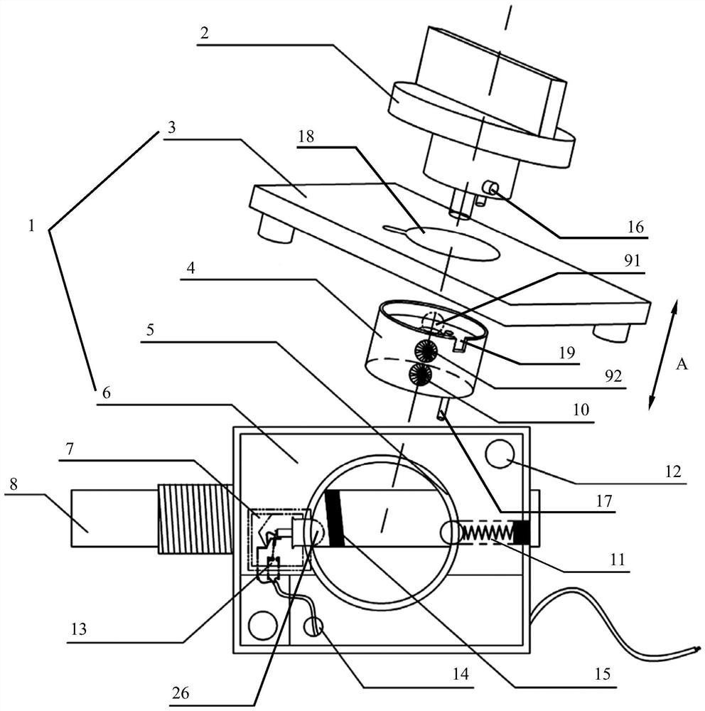
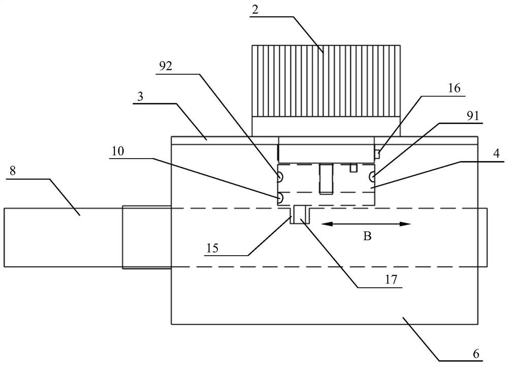
[0052] as attached figure 1 , 2 , 4 and 5, an embodiment of a program lock specifically includes: a lock body 1, a lock cylinder 4, a positioning component 5, a state feedback unit 7, a locking lever 8 and a locking component 11. The positioning part 5, the state feedback unit 7, and the locking part 11 are fixed inside the lock body 1 (the positioning part 5, the state feedback unit 7, and the locking part 11 can be integrally formed with the lock body 1, or can be packaged in a modular way and passed through screws. fixed), the lock rod 8 is installed in the lock body 1. The lock core 4 is arranged inside the lock body 1, and the positioning part 5 is arranged on the outer periphery of the lock core 4. One end of the locking part 11 can pass through the side of the positioning part 5. The first positioning groove 91. The unlocking and locking of the program lock is realized by the rotation of the lock core 4, and the lock core 4 simultaneously drives the lock bar 8 (the l...

Embodiment 2

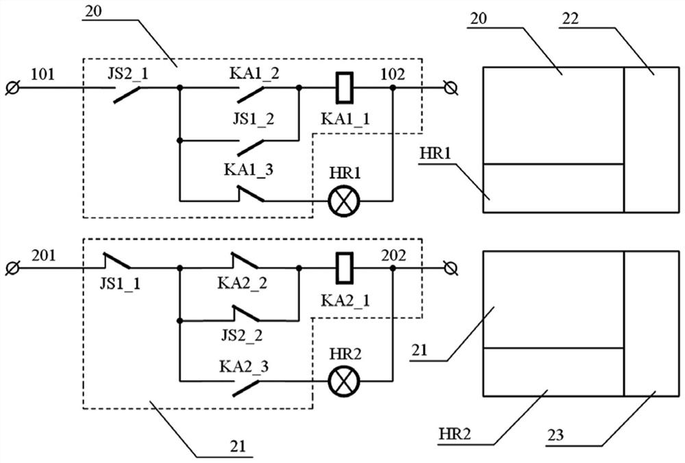
[0060] as attached Figure 6 As shown, the rotation of the lock cylinder 4 is used to change the state in the embodiment 1, and the state of the limit switch is changed by the movement of the lock rod 8 in this embodiment. In this embodiment, a stroke groove 10 is provided on the side of the lock lever 8 at a position corresponding to the state feedback unit 7 , and the state feedback unit 7 obtains the positioning state of the unlocked or locked position of the program lock through the stroke groove 10 . The state feedback unit 7 adopts a travel switch, and the travel switch is provided with a contact 26 matched with the travel groove 10 . When the locking bar 8 is in the unlocked position and during telescopic movement, the contact 26 is pressed by the side of the locking bar 8 . When the lock cylinder 4 reaches the locked position, the contact 26 snaps into the stroke groove 10, the stroke of the stroke switch is released, and the state of the auxiliary contact 13 of the s...

Embodiment 3

[0062] as attached Figure 7 As shown, unlike Embodiments 1 and 2, which realize the state feedback of the program lock by adding a travel switch, this embodiment realizes the state feedback through optical signals. In this embodiment, an emitting light source 28 is arranged in the stroke groove 10 , and a photoresistor VR1 is arranged at a position corresponding to the emitting light source 28 inside the state feedback unit 7 . When the bottom of the state feedback unit 7 blocks the emission light source 28, the emission light source 28 cannot irradiate the photoresistor VR1, and when the lock lever 8 moves until the photoresistor VR1 is facing the travel groove 10, the emission light source 28 irradiates the photoresistor VR1 , and the resistance value changes at the same time, so as to realize the state feedback of the program lock. The emitting light source 28 can also be replaced by a photoelectric emitting tube, and the photosensitive resistor VR1 can be replaced by a p...


PUM


Abstract

The invention provides a programlock, an interlocking system including the same and a controlling method thereof. A positioningcomponent, a state feedback unit and a lock component are fixed into a lock body, and a lock rod is arranged in the lock body in apenetrating mode. A lock core is arranged in the lock body, the positioning component is arranged on the outer periphery of the lock core, oneend of the lock component can penetrate through the side surface of the positioning component, and a first positioning groove which corresponds to the position of the lock component is formed in the side surface of the lock core. Unlocking and locking of the programlock are achieved through the rotation of the lock core, and the lock core drives the lock rod to extend and retract at the same time.In the rotation process of the lock core, the lock component abuts against the side surface of the lock core, and the lock component is clamped intothe first positioning groove when the lock core rotates in place, so that positioning of the unlock position or the lock position of the programlock is realized. While the unlock position or the lock position of the programlock is positioned, the state feedback unit outputs unlocking or locking indication signals of the programlock. The programlock,the interlocking system including the same and the controlling method thereof can solve the technical problems thata traditional programlockhas no state feedback, has a complex operating process, requiresprofessionaloperating staff to memorize processes repeatedly, and has low operating efficiency.

Description

technical field [0001] The invention relates to the technical field of electrical equipment, in particular to a program lock with state feedback applied to a power system, including an interlocking system of the program lock and a control method thereof. Background technique [0002] Electrical misoperation in the power system is a frequent failure that threatens the safe operation of power equipment. It may cause large-scale power outages, damage to power equipment, system oscillation and collapse, and even casualties. In order to realize the safe and reliable operation of power equipment, the electric power department enforces that high-voltage switchgear must be equipped with anti-misoperation devices to meet the requirements of "five preventions", namely: prevent mis-opening and mis-closing circuit breakers, and prevent load-closing isolating switches , Prevent strayed into the charged interval, prevent the live wire from being connected to the ground wire, and prevent t...

Claims


Application Information

Patent Timeline
Patent Type & Authority Patents(China)
IPC IPC(8): E05B65/00E05B15/00E05B17/22H01H9/20
CPCE05B15/00E05B17/226E05B65/00H01H9/20
Inventor 戴绍俊敬华兵谢晟刘更强杨丁丁陈祥王敏辉胡盛
Owner ZHUZHOU CSR ELECTROMECHANICAL TECH
Why Eureka
Try Eureka