Anti-explosion device and method for top of switch cabinet

An explosion-proof device and switchgear technology, applied in switchgear, switchgear settings, electrical components, etc., can solve the problems of air pressure not being released in time, slow uniform speed, and increase in air pressure.

Pending Publication Date: 2019-01-22
GUIZHOU POWER GRID CO LTD
View PDF0 Cites 5 Cited by
  • Summary
  • Abstract
  • Description
  • Claims
  • Application Information

AI Technical Summary

Problems solved by technology

[0002] Generally, there are busbar room, overvoltage device, relay instrument room, isolating switch, circuit breaker room, etc. in the switchgear. Since various components and electrical appliances are located in the switchgear, the operating space is small, and these electrical components generate a lot of heat when they are energized. It will cause the internal temperature of the switchgear to rise and the air pressure to increase, but the air pressure cannot be released in time, which will cause the switchgear to explode, bringing huge safety hazards and economic losses
[0003] The explosion-proof of the existing switchgear usually adopts a pressure relief valve or an explosion-proof membrane, and the pressure relief of the pressure relief valve and the explosion-proof membrane is a uniform and slow process. When the gas in the cabinet expands rapidly and the air pressure is large, it cannot be quickly released pressure, it will still explode, and the existing explosion-proof membrane is not easy to replace after damage

Method used


Image

  • Anti-explosion device and method for top of switch cabinet
  • Anti-explosion device and method for top of switch cabinet
  • Anti-explosion device and method for top of switch cabinet

Examples


Embodiment Construction

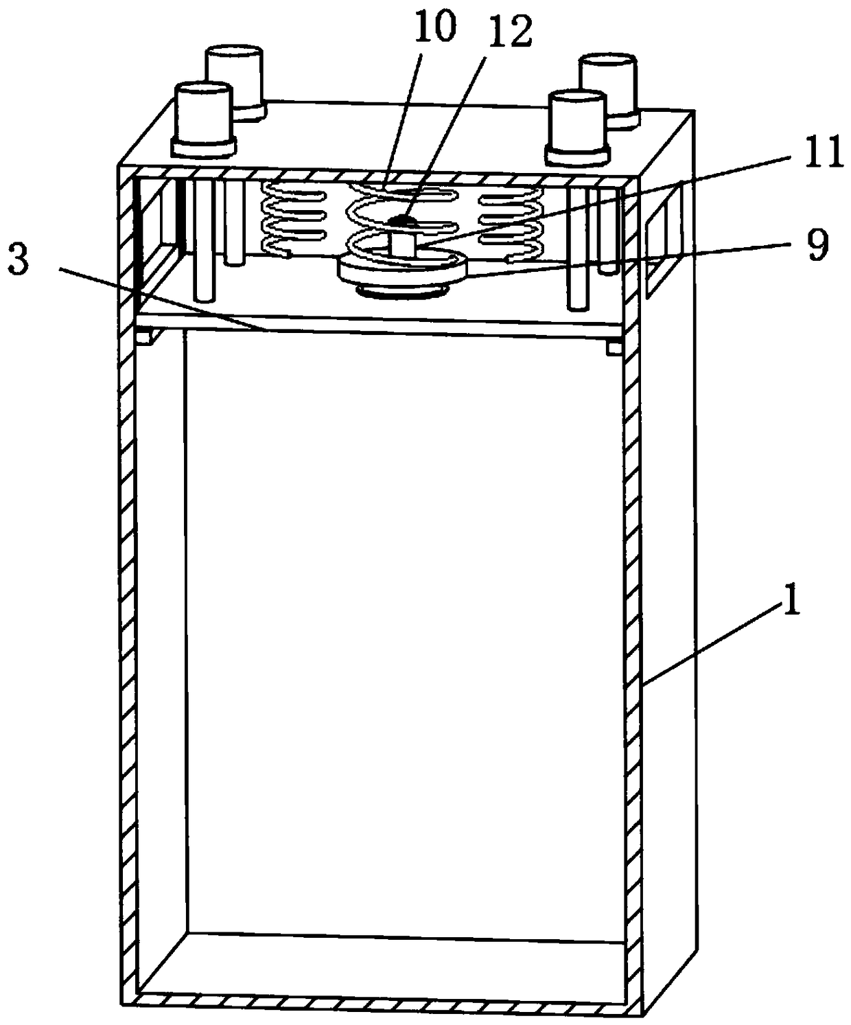
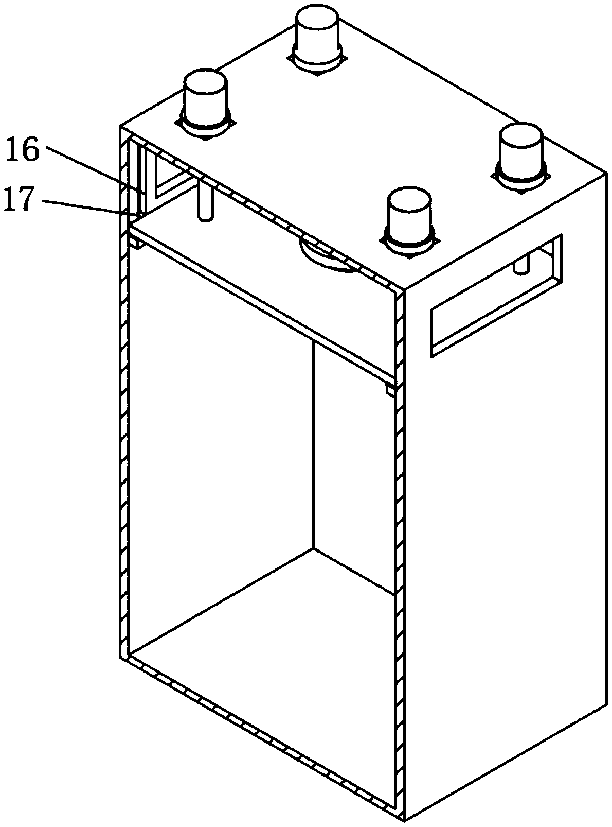
[0020] Below in conjunction with accompanying drawing and specific embodiment the invention is further introduced:

[0021] refer to Figure 1 to Figure 4 According to the present invention, an explosion-proof device at the top of a switch cabinet comprises: a cabinet body 1, and a partition plate 3 that can slide along the height direction of the cabinet body 1 is arranged in the cabinet body 1, and the partition board 3 divides the cabinet body 1 into upper space and The lower space, wherein the lower space is used to install various electrical components, and an explosion-proof membrane 8 for releasing the inflation gas in the lower space is installed on the partition plate 3 . Preferably, a threaded through hole 6 is formed in the middle of the partition 3, and a threaded ring 7 is threaded in the threaded through hole 6, and an explosion-proof membrane 8 is fixedly installed in the threaded ring 7, so that after the explosion-proof membrane 8 bursts, it can Quick change....


PUM


Abstract

The invention discloses an anti-explosion device and method for top of a switch cabinet including a cabinet and a partition plate, An explosion-proof membrane is arranged on that partition plate for releasing the expand gas in the lower space of the partition plate, the partition plate is connected with the top of the inner wall of the cabinet body through a cushioning assembly, the cushioning assembly includes a baffle, a First spring, an Electric push rod and a contact switch, when the expansion gas pressure in the lower space of the separator exceeds the set pressure value of the explosion-proof film, the expansion gas is discharged from the explosion-proof film and pushed against the baffle, the baffle plate is moved upward to compress the first spring and to close the contact switch at a set stroke, thereby controlling the electric push rod to contract its push rod to move the partition plate upward, and the expanded gas is discharged outwardly from the exhaust windows arranged onboth sides of the upper part of the cabinet body; The device can quickly release the expanding gas when it is generated in the switch cabinet, thus effectively avoiding the explosion damage of the switch cabinet.

Description

technical field [0001] The invention relates to an explosion-proof device and method at the top of a switch cabinet, belonging to the technical field of electrical equipment. Background technique [0002] Generally, there are busbar room, overvoltage device, relay instrument room, isolating switch, circuit breaker room, etc. in the switchgear. Since various components and electrical appliances are located in the switchgear, the operating space is small, and these electrical components generate a lot of heat when they are energized. It will cause the internal temperature of the switchgear to rise and the air pressure to increase, but the air pressure cannot be released in time, which will cause the switchgear to explode, bringing huge potential safety hazards and economic losses. [0003] The explosion-proof of the existing switchgear usually adopts a pressure relief valve or an explosion-proof membrane, and the pressure relief of the pressure relief valve and the explosion-p...

Claims


Application Information

Patent Timeline
Patent Type & Authority Applications(China)
IPC IPC(8): H02B13/025
CPCH02B13/025
Inventor 王波卢兴福王勋范勇樊三军谢扬华曹俊李宏才龙波胡茂
Owner GUIZHOU POWER GRID CO LTD
Why Eureka
Try Eureka