Reversing valve element

A reversing valve and valve core technology, which is applied to fluid pressure actuating devices, servo motor components, mechanical equipment, etc., can solve the problems of inconvenient use and operation, and the hydraulic reversing valve core cannot work normally, so as to save oil. amount of effect

Active Publication Date: 2015-03-25
NINGBO LONG WALL FLUID KINETIC SCI TECH
View PDF10 Cites 3 Cited by
  • Summary
  • Abstract
  • Description
  • Claims
  • Application Information

AI Technical Summary

Problems solved by technology

[0003] However, in the above-mentioned hydraulic reversing spool, when the oil control port fails, the hydraulic reversing spool will not work normally; in the above-mentioned manual reversing spool, due to the presence of hydraulic oil in the oil inlet passage in the valve stem, When the handle assembly pushes the valve stem, it will be resisted by the hydraulic oil in the oil inlet channel, which requires a lot of effort to overcome the resistance, which is inconvenient to use and operate

Method used


Image

  • Reversing valve element
  • Reversing valve element

Examples


Embodiment

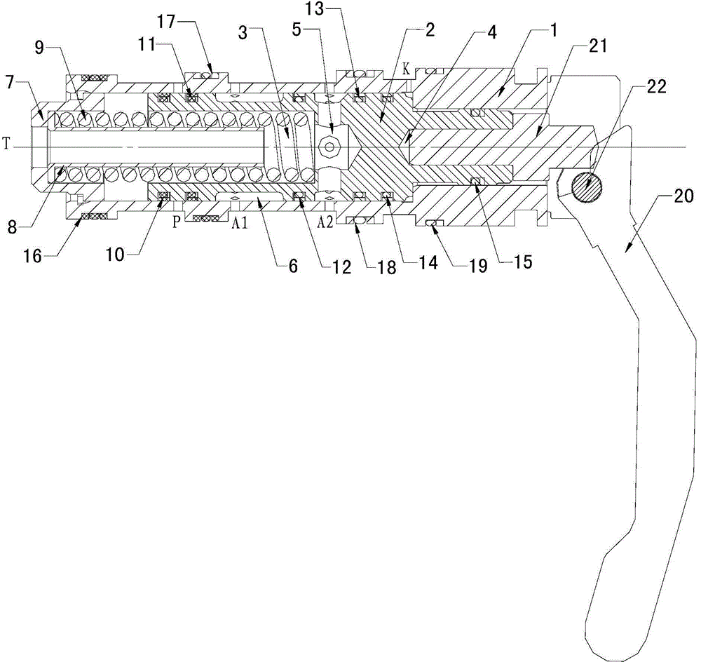
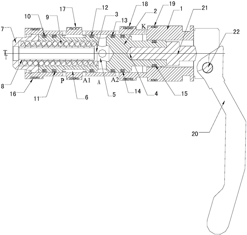
[0014] Embodiment: A reversing valve core, including a valve sleeve 1 and a valve stem 2, the valve stem 2 is located in the valve sleeve 1 and coaxially arranged with the valve sleeve 1, and the front part of the valve stem 1 is provided with a first concave cavity in the axial direction 3. The rear part of the valve stem 1 is provided with a second cavity 4 along the axial direction, the valve stem 1 is provided with a connecting hole 5 communicating with the first cavity 3, and the front end of the valve sleeve 1 is provided with a hole extending into the first cavity 3. The elastic reset device, the rear end of the valve sleeve 1 is provided with a handle assembly extending into the second cavity 4, the inside of the elastic reset device communicates with the first cavity 3, and the outer wall of the valve stem 2 is provided with an annular communication groove 6, Valve sleeve 1 is provided with pressure oil port P, first working oil port A1, second working oil port A2 and ...


PUM


Abstract

The invention discloses a reversing valve element. The reversing valve element comprises a valve sleeve and a valve rod. The valve rod is located in the valve sleeve and is coaxial with the valve sleeve. A first cavity is axially formed in the front part of the valve rod, and a second cavity is axially formed in the rear part of the valve rod. A connecting hole communicated with the first cavity is formed in the valve rod. An elastic resetting device stretching into the first cavity is arranged at the front end of the valve sleeve, and a handle assembly stretching into the second cavity is arranged at the rear end of the valve sleeve. The interior of the elastic resetting device is communicated with the first cavity. An annular communicating groove is formed in the outer wall of the valve rod. A pressure oil port, a first working oil port, a second working oil port and an oil control port are sequentially formed at intervals in the valve sleeve from front to back. The reversing valve element has the advantages that both the hydraulic reversing function and the manual reversing function are achieved, and normal work can be guaranteed through the manual reversing function when the hydraulic reversing function fails; besides, the valve rod in the reversing valve element will not be resisted by hydraulic oil in the axial direction, manual reversing can be achieved with a little strength, and therefore use and operation are convenient.

Description

technical field [0001] The invention relates to a valve core, in particular to a reversing valve core. Background technique [0002] Existing reversing spools generally include two types: hydraulic reversing spools and manual reversing spools. The hydraulic reversing spool usually includes a valve sleeve and a valve stem located in the valve sleeve and coaxially arranged with the valve sleeve. One end of the valve sleeve is provided with a working oil port, and the other end of the valve sleeve is provided with an oil control port. The side wall of the valve sleeve There are pressure oil port and liquid return port, wherein the liquid return port is close to the oil control port, and the pressure oil port is close to the working oil port. An oil inlet channel connected with the working oil port is arranged in the valve stem along the axial direction. There is an opening connected with the oil inlet passage; in the initial state, the opening on the valve stem connects the oi...

Claims


Application Information

Patent Timeline
Patent Type & Authority Applications(China)
IPC IPC(8): F15B13/02
CPCF15B13/02
Inventor 应永华何海瑞梁益来邬光军宋磊
Owner NINGBO LONG WALL FLUID KINETIC SCI TECH
Why Eureka
Try Eureka