Novel automatic bearing machining equipment

A bearing processing and automatic technology, applied in other manufacturing equipment/tools, manufacturing tools, etc., can solve the problems of high labor cost, cost reduction, complex mold, etc., and achieve the effect of improving production efficiency

Active Publication Date: 2019-02-15
浙江飞宇自动化科技股份有限公司
View PDF11 Cites 0 Cited by
  • Summary
  • Abstract
  • Description
  • Claims
  • Application Information

AI Technical Summary

Problems solved by technology

At present, the multiple processing procedures of the shaft sleeve are mainly processed in sections, which requires more labor, high labor costs, low production efficiency, and high defective rate
Today, with rising labor costs and people's increasingly high quality requirements, traditional processing methods can no longer meet the needs of today's market.
The processing accuracy of the shaft sleeve is an important factor determining the noise level of the indoor unit. The precision of the workpiece produced by the traditional processing method is not high, which cannot meet the user's requirements for low noise and low vibration of the air conditioner. security incident
[0003] In order to solve the above technical problems, although some automatic machines have been proposed in the prior art, the current automatic machines are only suitable for the processing of bearings with fixed diameters, and for the processing of bearings with different diameters, it is very complicated to replace different molds, which still cannot improve the work efficiency. Efficiency, not conducive to further cost reduction

Method used


Image

  • Novel automatic bearing machining equipment
  • Novel automatic bearing machining equipment
  • Novel automatic bearing machining equipment

Examples


Embodiment Construction

[0019] Specific embodiments of the present invention will be further described in detail below. It should be understood that the description of the embodiments of the present invention here is not intended to limit the protection scope of the present invention.

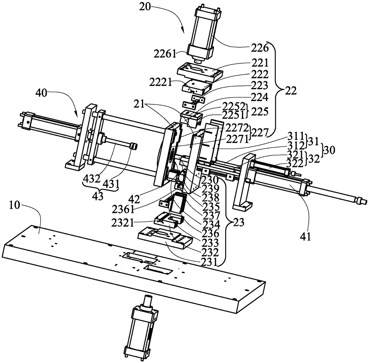
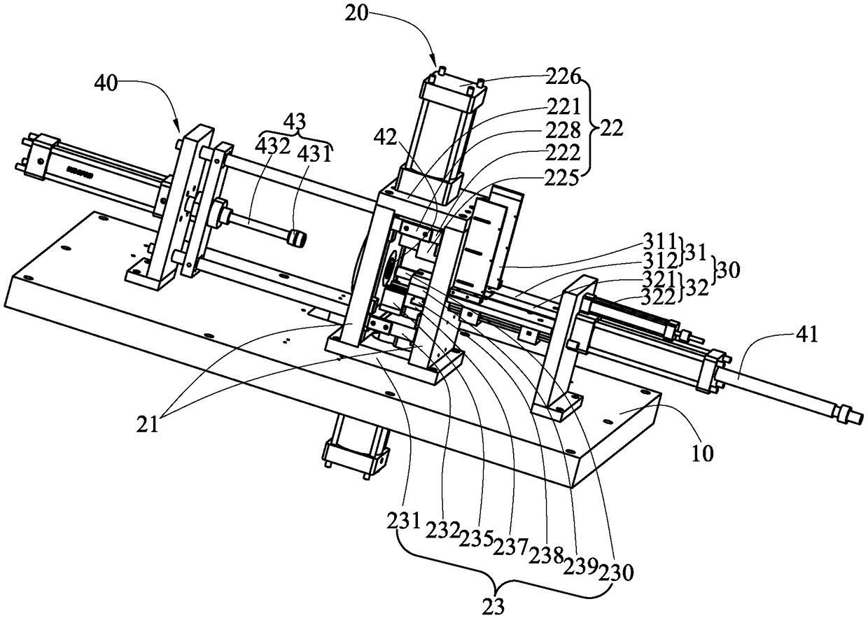
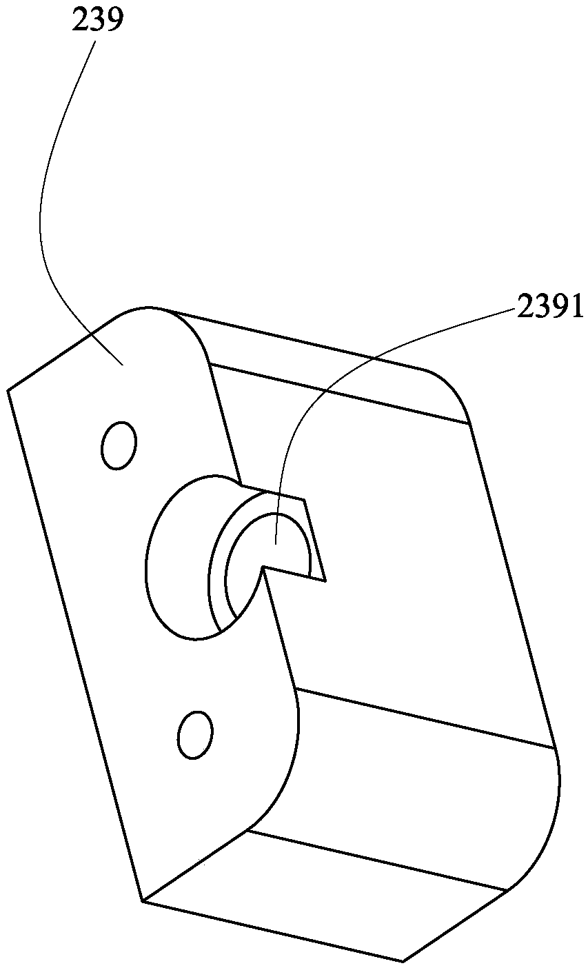
[0020] like Figure 1 to Figure 3 As shown, it is a structural schematic diagram of the new automatic bearing processing equipment provided by the present invention. The new automatic bearing processing equipment includes a frame 10, a rolling mechanism 20 arranged on the frame 10, a feeding mechanism 30 arranged on the frame 10, and a rolling mechanism 20 arranged on the frame 10. The shaping mechanism 40 on the top, and a control device 50 that controls the orderly operation of the rolling mechanism 20, the feeding mechanism 30, and the shaping mechanism 40. It is conceivable that, as a device for processing shaft sleeves, it also includes other functional modules, such as installation components, motor fixing com...


PUM


Abstract

The invention provides novel automatic bearing machining equipment, which comprises a rack and a coiling mechanism. The coiling mechanism comprises an upper coiling mechanism and a lower coiling mechanism; the upper coiling mechanism comprises an upper supporting seat, an upper installation plate, a first installation strip, an upper clamping plate, and an upper coiling mold; the upper installation plate comprises a first fixing inserting hole; the first installation strip is fixedly arranged in the first fixing jack in an inserted mode, and the first installation strip has the same sectionalshape with the first fixing jack; the upper coiling mold is fixed to the upper clamping plate and comprises an upper prefabricated mold and an upper coiling mold; the upper prefabricated mold is provided with an arc-shaped surface, and the coiling mold is provided with a semicircular surface; the lower coiling mechanism comprises a lower supporting seat, a lower installation plate, a second installation strip, a lower clamping plate, a lower coiling mold, a supporting pad, a fixing plate, a third installation strip, a lower prefabricated mold, and a core rod; and the axial direction of the core rod is coincided with the circular central axis formed by the upper coiling mold and lower coiling mold. According to the novel automatic bearing machining equipment, the production efficiency can be improved.

Description

technical field [0001] The invention belongs to the technical field of mechanical equipment, in particular to a novel automatic bearing processing equipment. Background technique [0002] The shaft sleeve is one of the commonly used mechanical parts in mechanical equipment. The processing of the shaft sleeve requires drilling, tapping, milling, chamfering, and reaming to process the shaft sleeve blank into the required workpiece shape. At present, the multiple processing procedures of the shaft sleeve are mainly processed in sections, which requires more labor, high labor costs, low production efficiency, and high defective rate. Today, with rising labor costs and people's higher and higher quality requirements, the traditional processing methods obviously cannot meet the needs of today's market. The processing accuracy of the shaft sleeve is an important factor determining the noise level of the indoor unit. The precision of the workpiece produced by the traditional proces...

Claims


Application Information

Patent Timeline
IPC IPC(8): B23P23/00
CPCB23P23/00
Inventor 李四根
Owner 浙江飞宇自动化科技股份有限公司
Why Eureka
Try Eureka