Projection equipment

A technology of projection equipment and mounting boards, which is applied in optics, instruments, projection devices, etc., can solve the problems affecting the size of the lens, the size of the lens, and the limited work requirements of optical-mechanical components, so as to reduce resonance and noise and increase structural rigidity. Effect

Inactive Publication Date: 2019-04-02
QINGDAO HISENSE LASER DISPLAY CO LTD
View PDF7 Cites 2 Cited by
  • Summary
  • Abstract
  • Description
  • Claims
  • Application Information

AI Technical Summary

Problems solved by technology

For projection lenses, the incident light aperture will affect the size of the lens. If the incident light aperture is large, the lens will be larger and the light collection requirements will be high, which will not only increase the volume of the entire lens group, but also detrimental to the optical performance of the lens the design of
With the improvement of miniaturization requirements, the volume of the projection lens is getting smaller and smaller through the design of the number of lenses and the shape of the surface. However, the interior of the optical-mechanical component is limited by the working requirements of the illumination optical path and the DMD light valve, so it is difficult to shrink synchronously. A module part will not match exactly when it is connected and fixed

Method used


Image

  • Projection equipment
  • Projection equipment
  • Projection equipment

Examples


Embodiment Construction

[0020] In order to make the purpose, technical solutions and advantages of the embodiments of the present invention clearer, the technical solutions in the embodiments of the present invention will be clearly and completely described below in conjunction with the drawings in the embodiments of the present invention. Obviously, the described embodiments It is a part of embodiments of the present invention, but not all embodiments. Based on the embodiments of the present invention, all other embodiments obtained by persons of ordinary skill in the art without creative efforts fall within the protection scope of the present invention.

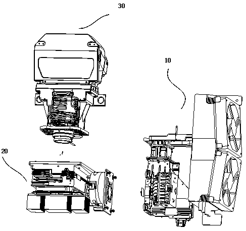
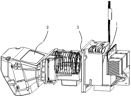
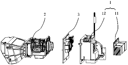
[0021] figure 2 It is a schematic structural diagram of the projection device provided by Embodiment 1 of the present invention. image 3 yes figure 2 An exploded schematic of the projection device in . Figure 4 It is a schematic structural diagram of the galvanometer assembly in the projection device provided by Embodiment 1 of the present ...


PUM


Abstract

The invention provides projection equipment, which comprises a light machine assembly, a lens assembly and an installing plate, wherein the installing plate is provided with a first side and a secondside; the first side is fixedly connected with the light machine assembly; the second side is fixedly connected with the lens assembly; and a vibration mirror is also arranged on the installing plate.The goal of fixing the light machine assembly and the lens assembly together can be achieved; the structure requirements of small-size projection equipment are met; meanwhile, the projection equipment is also used for installing a vibration mirror; the reservation of a space inside the light machine assembly is not needed; the volume reduction of the light machine assembly is also facilitated; and the integral miniaturization of the projection equipment is also facilitated.

Description

technical field [0001] The present invention relates to the field of projection equipment, in particular to a projection equipment. Background technique [0002] With the continuous development of science and technology, projection devices have been more and more widely used due to their advantages of large screen size and good visual effects. [0003] figure 1 A schematic structural diagram of a projection device in the prior art is shown, such as figure 1 As shown, the projection device includes a light source module 10 , an optical machine module 20 , and a projection lens 30 . With the improvement of brightness requirements, the light source module 10 generally includes a laser component, such as a blue laser, or a blue laser and a red laser, or three-color lasers. The light source module 10 is where the heat source of the projection device is located, and is usually equipped with air-cooled or liquid-cooled heat dissipation devices. The light beam emitted by the lig...

Claims


Application Information

Patent Timeline
IPC IPC(8): G03B21/14G03B21/28G02B26/08
CPCG02B26/0833G03B21/14G03B21/28
Inventor 黄永达李建军石龙飞
Owner QINGDAO HISENSE LASER DISPLAY CO LTD
Why Eureka
Try Eureka