
Method for transplanting circuit board

A technology of circuit boards and sub-circuit boards, which is applied in the direction of assembling printed circuits with electrical components, can solve problems such as bending deformation, insufficient rigidity, damage, etc., and achieve the effect of strong structural rigidity and increased yield

Active Publication Date: 2015-05-20
TRIPOD WUXI ELECTRONICS
View PDF3 Cites 6 Cited by
  • Summary
  • Abstract
  • Description
  • Claims
  • Application Information

AI Technical Summary

Problems solved by technology

However, due to the insufficient rigidity of the upper and lower side strips used to frame the sub-circuit board, it is easy to be bent or even damaged during the manufacturing process or the assembly process of the sub-circuit board.
In addition, since the two side strips are two independent components manufactured separately, manufacturing tolerances are likely to occur between the two side strips of the same multi-circuit board, and the bending deformation and expansion and shrinkage differences of the two side strips may be caused by insufficient rigidity , all of the above reasons will affect the accuracy of multi-circuit board assembly and bonding and the reliability of subsequent manufacturing processes

Method used


Image

  • Method for transplanting circuit board
  • Method for transplanting circuit board
  • Method for transplanting circuit board

Examples


Embodiment Construction

[0041] The aforementioned and other technical contents, features and effects of the present invention will be clearly presented in the following detailed description of the embodiments with reference to the accompanying drawings. The directional terms mentioned in the following embodiments, such as "upper", "lower", "front", "rear", "left", "right", etc., are only referring to the directions of the accompanying drawings. Accordingly, the directional terms used are illustrative, not limiting, of the invention. Also, in the following embodiments, the same or similar components will be given the same or similar symbols.

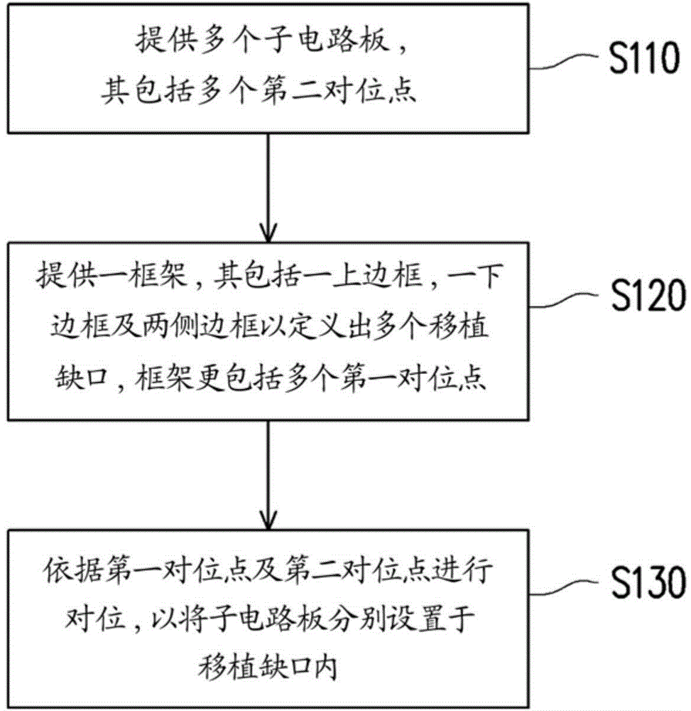
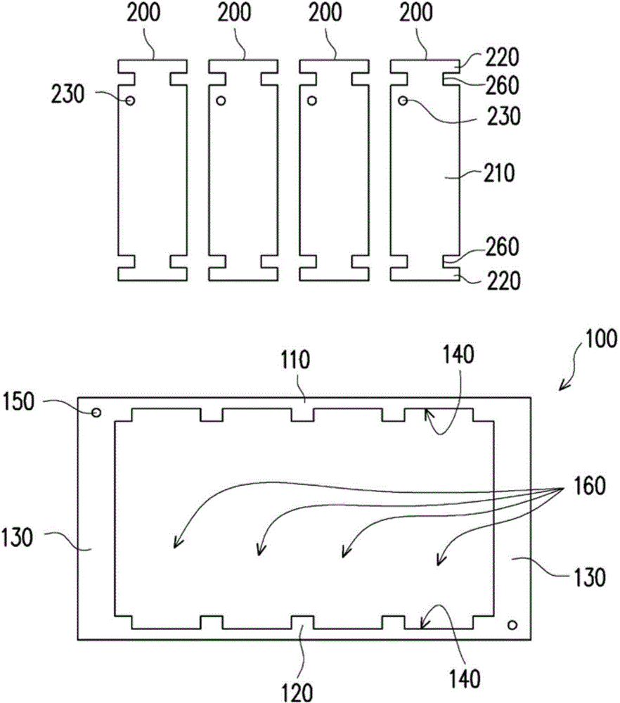
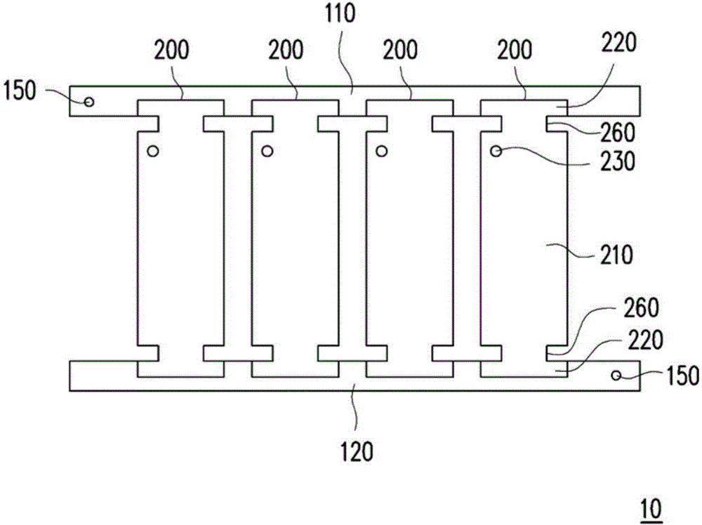
[0042] figure 1 It is a schematic flow diagram of a method for transplanting a circuit board according to an embodiment of the present invention. figure 2 It is a schematic diagram of a frame and a sub-circuit board according to an embodiment of the present invention. Please also refer to figure 1 as well as figure 2 The method for transplanting circuit b...


PUM


Abstract

The invention discloses a method for transplanting a circuit board. The method comprises the following steps: a plurality of sub circuit boards which are confirmed as qualified ones through layer offset test and electrical test are provided, wherein each sub circuit board is composed of a body, a plurality of foldable connecting rods, a plurality of clamping parts and a plurality of first alignment points, and each foldable connecting rod protrudes from the body and is connected with the corresponding clamping part; a framework is provided, wherein the framework is composed of an upper frame, a lower frame, two side frames, a plurality of clamping openings and a plurality of second alignment points, the clamping openings are disposed in the inner edges of the upper frame and the lower frame, the second alignment points are arranged on the upper frame and the lower frame, and the side frames are connected with the upper frame and the lower frame to jointly define a plurality of transplanting gaps; and the first alignment points and the second alignment points are aligned with each other to arrange the sub circuit boards in the transplanting gaps, and the clamping parts are embedded into the corresponding clamping openings to fix the sub circuit boards to the framework.

Description

technical field [0001] The invention relates to a method for implanting semiconductors, and in particular to a method for implanting circuit boards. Background technique [0002] In the current manufacturing method of circuit boards, one circuit substrate is usually made into a plurality of sub-circuit boards, so that the circuit substrate forms a multi-circuit board. However, sub-circuit boards with slight defects are unavoidably produced during the production process, and it is a waste of resources to scrap the defective products. In view of this, some manufacturers of multi-circuit boards will conduct electrical tests on the sub-circuit boards of multi-circuit boards, and then reassemble multiple sub-circuit boards that are determined to be good products after electrical tests into new multi-circuit boards , so that the sub-circuit boards on these multi-connection circuit boards after reorganization are all usable good products. [0003] However, the current technology ...

Claims


Application Information

Patent Timeline
IPC IPC(8): H05K3/36
CPCH05K3/36
Inventor 林哲永张阿松杨伟雄
Owner TRIPOD WUXI ELECTRONICS
Learn More