A shell processing punch

A casing and punching technology, applied in metal processing equipment, manufacturing tools, perforating tools, etc., can solve problems such as hidden dangers, and achieve the effect of avoiding hidden dangers and improving work efficiency.

Active Publication Date: 2020-06-02
重庆全能电器有限公司
View PDF14 Cites 0 Cited by
  • Summary
  • Abstract
  • Description
  • Claims
  • Application Information

AI Technical Summary

Problems solved by technology

However, in the above working method, when the manipulator is inserted into the punch press, the punch is still working, and the punch may punch the manipulator, resulting in a great potential safety hazard

Method used


Image

  • A shell processing punch
  • A shell processing punch
  • A shell processing punch

Examples


Embodiment Construction

[0017] The following is further described in detail through specific implementation methods:

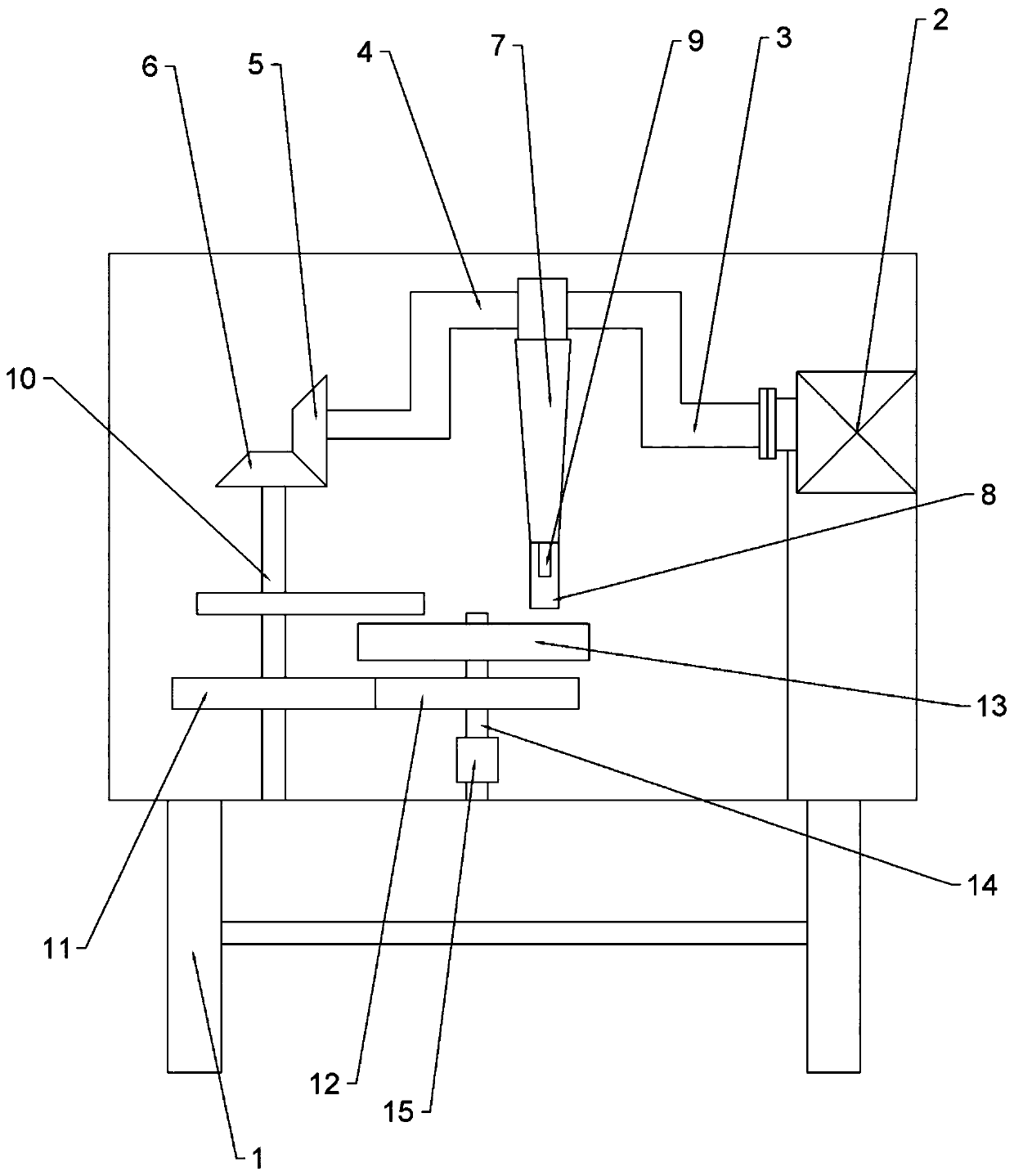
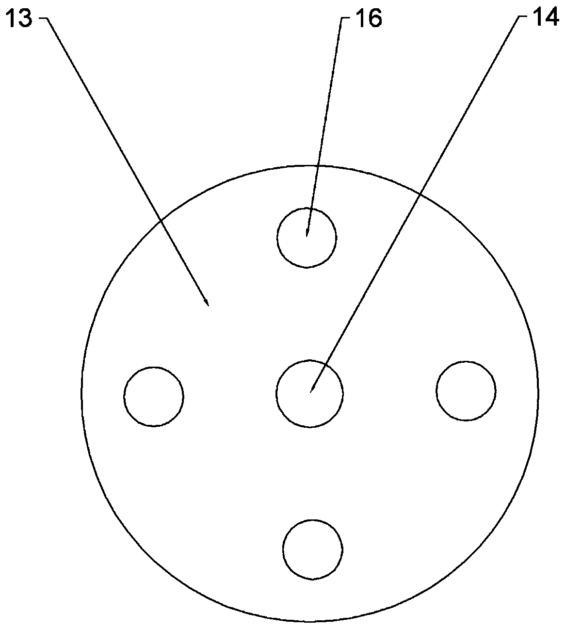
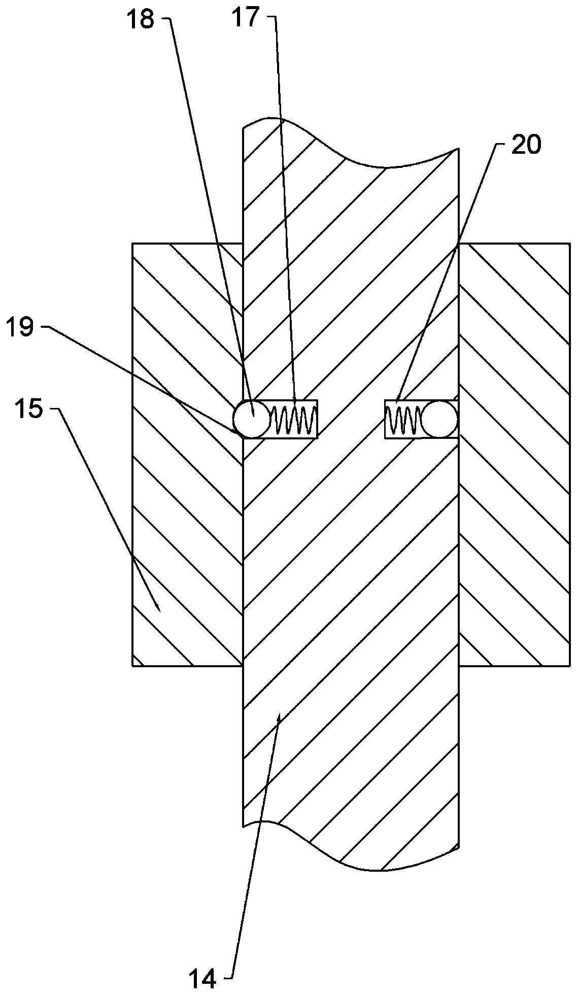
[0018] The reference signs in the drawings of the description include: frame 1, motor 2, crankshaft 3, crankshaft journal 4, first bevel gear 5, second bevel gear 6, connecting rod 7, slideway 8, punch 9, rotating shaft 10. Incomplete gear 11, complete gear 12, turntable 13, connecting shaft 14, limit block 15, cavity 16, spring 17, steel ball 18, arc groove 19, groove 20, feed channel 21, discharge Mouth 22, baffle plate 23, connecting rod 24, cam 25.

[0019] The embodiment is basically as attached figure 1 Shown: a casing processing punching machine, including a frame 1, a casing, a punch 9, a power source, a crankshaft 3, a connecting rod 7, a first bevel gear 5 and a second bevel gear 6. The frame 1 is fixedly connected to the casing. In this solution, the power source is the motor 2, and the motor 2 is fixed on the inner wall of the housing. The output shaft of the motor 2 ...


PUM


Abstract

The invention belongs to the field of punching devices adopting rigid equipment or tools, and particularly discloses a punching machine for motor shell machining. A rack and a shell body are fixedly connected, and a power source and the shell body re fixedly connected. An output shaft of a motor is connected with one end of a crankshaft, and the crankshaft is rotationally connected with the shellbody. One end of a connecting rod is hinged to a puncher pin. One end of the crankshaft is connected with a first bevel gear, a second bevel gear is rotationally connected with the rack, and the firstbevel gear is engaged with the second bevel gear. The second bevel gear is coaxially connected with a rotating shaft, the rotating shaft is coaxially connected with an incomplete gear, a complete gear is rotationally connected to the rack, and the incomplete gear is engaged with the complete gear. The complete gear is coaxially and fixedly connected with a connecting shaft, the connecting shaft is coaxially and fixedly connected with a rotating disc, and the rotating disc and the shell body are in running fit. Four concave cavities are formed in the upper end face of the rotating disc and areevenly arranged in the circumferential direction of the rotating disc, molds are connected in the four concave cavities, and the puncher pin and one concave cavity are in the same vertical direction.By means of the punching machine, the machining efficiency can be improved, and potential safety hazards are reduced.

Description

technical field [0001] The invention belongs to the field of punching devices using rigid equipment or tools, and specifically discloses a casing processing punch. Background technique [0002] The motor casing (referred to as the casing) is a part used to accommodate all the components of the motor. Its main purpose is to protect the motor components from rain, corrosion, rust, etc. Because of its protection, the life of the motor can be longer, and it can be used in suitable operating under conditions. During the processing of the casing, it needs to be punched with a punch. [0003] The punching machine is a punching press, which can punch, form and shape the workpiece through the mold. In the use of punch presses, most of the existing loading and unloading processes are manual. When manual punching is adopted, the punching machine generally cannot be operated continuously. It is necessary to place the casing first and then start the punch for punching, which leads to ...

Claims


Application Information

Patent Timeline
Patent Type & Authority Patents(China)
IPC IPC(8): B21D28/34B21D28/36H02K15/14
CPCB21D28/34B21D28/36H02K15/14
Inventor 左陶
Owner 重庆全能电器有限公司
Why Eureka
Try Eureka