A preparation method of a microcavity coupling system and a microwave photonic filter

A coupling system and microcavity technology, applied in the coupling of optical waveguides, instruments, optics, etc., can solve the problems that the suppression ratio cannot reach a high level stably, the Q value of the microcavity is difficult to further improve, and the coupling conditions are harsh.

Inactive Publication Date: 2020-10-27
JINAN UNIVERSITY
View PDF9 Cites 0 Cited by
  • Summary
  • Abstract
  • Description
  • Claims
  • Application Information

AI Technical Summary

Problems solved by technology

However, due to the difficulty of processing technology, the limitation of material loss, and the harsh coupling conditions, it is difficult to further improve the Q value of the current microcavity. Therefore, the bandwidth of most microcavity filters is still at the gigahertz GHz level, and the rejection ratio cannot be stabilized. Reaching a higher level, the processing and manufacturing process is also more complicated

Method used


Image

  • A preparation method of a microcavity coupling system and a microwave photonic filter
  • A preparation method of a microcavity coupling system and a microwave photonic filter
  • A preparation method of a microcavity coupling system and a microwave photonic filter

Examples


Embodiment Construction

[0029] The present invention will be further described below in conjunction with drawings and embodiments.

[0030] see figure 1 , one A preparation method of a microcavity coupling system, comprising:

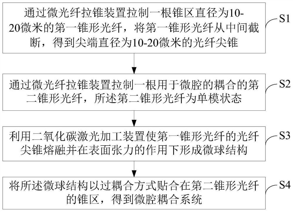
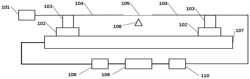
[0031] S1, drawing a first tapered optical fiber with a diameter of 10-20 microns in the tapered region through a micro-fiber tapering device, cutting the first tapered optical fiber from the middle to obtain a fiber tip 203 with a tip diameter of 10-20 microns ; see figure 2, the micro-fiber taper device includes a DFB laser 101, an electric displacement platform 107, two identical electric displacement sliders 102, two identical first optical fiber clamps 103, a data acquisition card 110, a first computer 109, an electric displacement A platform controller 108 and a hydrogen-oxygen flame high-temperature spray gun 106 for heating the single-mode optical fiber; wherein the two electric displacement sliders 102 are installed on the guide rail of the electric displacement ...


PUM

PropertyMeasurementUnit
diameteraaaaaaaaaa

Abstract

The invention discloses a microwave photon filter which comprises a radio frequency amplifier, an erbium-doped fiber amplifier, a tunable optical attenuator, a microcavity coupling system, a spectrumanalyzer and a photoelectric detector. Narrow-linewidth optical carrier wave emitted by a tunable laser passes through a polarization controller and then is processed by DP- MZM into double-side-bandlight wave, and after the double-side-band light wave is amplified by the erbium-doped fiber amplifier, the light power of the double-side-band light wave entering the micro-cavity coupling system iscontrolled by the tunable optical attenuator; wherein an optical signal output by the micro-cavity coupling system is divided into two paths, one path enters the spectrum analyzer for monitoring sideband information of the optical signal in real time, and the other path enters a VNA for monitoring a radio frequency spectrum of the optical signal after passing through the photoelectric detector; meanwhile, the VNA outputs a radio frequency signal, and the output radio frequency signal is loaded to the DP-MZM through an orthogonal mixer after passing through the radio frequency amplifier, and modulation of a sideband is realized. The microcavity coupling system is obtained by attaching the microsphere structure to the conical region of the second conical optical fiber in an over-coupling manner.

Description

technical field [0001] The invention relates to the technical field of micro-nano optical devices, in particular to a preparation method of a micro-cavity coupling system and a microwave photon filter. Background technique [0002] Most of the traditional microwave photonic filters are realized based on fiber nonlinear effects, such as parametric amplification and frequency transfer. Limited by the structure and performance of optical fiber devices, most of these microwave photonic filters have insufficient bandwidth. In recent years, due to the theoretically high quality factor of optical microcavities, it is easier to obtain optical modes with extremely narrow linewidths, and optical devices based on microcavity structures have attracted widespread attention. microwave photonic filter. Compared with the traditional microwave photonic filter, the microwave photonic filter based on the microcavity structure has the characteristics of simple and light structure, and is easi...

Claims


Application Information

Patent Timeline
Patent Type & Authority Patents(China)
IPC IPC(8): G02B6/26G02F1/01
CPCG02B6/262G02F1/011G02F1/0121
Inventor 李建平余贝
Owner JINAN UNIVERSITY
Why Eureka
Try Eureka