Braking device for permanent-magnet direct-driving roller

A braking device and permanent magnet direct drive technology, which is applied in the direction of transportation, packaging, conveyors, etc., can solve the problems of permanent magnet direct drive drum braking, etc., and achieve the effect of reducing spare parts, reducing costs, and simple maintenance

Pending Publication Date: 2019-04-19
JIANGSU JIAXUAN INTELLIGENT IND TECH CO LTD
View PDF0 Cites 2 Cited by
  • Summary
  • Abstract
  • Description
  • Claims
  • Application Information

AI Technical Summary

Problems solved by technology

[0003] The invention proposes a braking device for a permanent magnet direct drive drum to solve the braking problem of the permanent magnet direct drive drum

Method used


Image

  • Braking device for permanent-magnet direct-driving roller
  • Braking device for permanent-magnet direct-driving roller

Examples


Embodiment Construction

[0013] The following will clearly and completely describe the technical solutions in the embodiments of the present invention with reference to the accompanying drawings in the embodiments of the present invention. Obviously, the described embodiments are only some, not all, embodiments of the present invention. Based on the embodiments of the present invention, all other embodiments obtained by persons of ordinary skill in the art without creative efforts fall within the protection scope of the present invention.

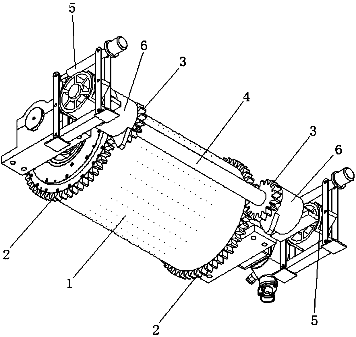
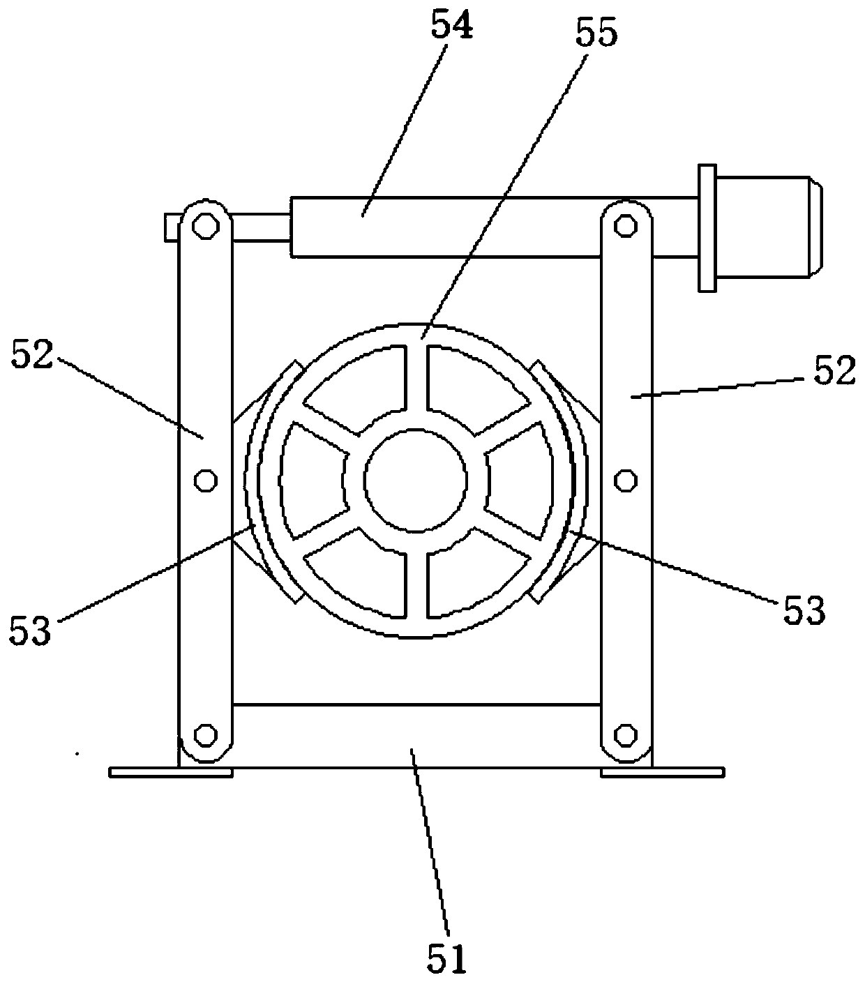
[0014] Such as figure 1 The braking device of the permanent magnet direct drive drum shown includes two large gears 2 fixedly installed on the drum 1 and two small gears 3 meshed with the large gears 2, the gear ratio of the large gears 2 to the small gears 3 The ratio is 3:1, the pinion 3 is fixedly connected with a rotating shaft 4, and two brakes 5 and two backstops 6 are symmetrically arranged on the rotating shaft 4. The backstop 6 adopts an NF backstop, which...


PUM


Abstract

The invention provides a braking device for a permanent-magnet direct-driving roller. The braking device for the permanent-magnet direct-driving roller comprises large gears fixedly installed on the roller and small gears meshing with the large gears, a rotation shaft is fixedly connected to the small gears, and brakes are arranged on the rotation shaft. The roller is driven by a belt to achieve transmission to drive the small gears to rotate, low-speed transmission is changed into high-speed transmission, the brakes and backstops are installed on the high-speed shaft, and the braking problemof the permanent-magnet direct-driving roller is effectively solved.

Description

technical field [0001] The invention belongs to the technical field of belt conveyors, and in particular relates to a braking device for a permanent magnet direct drive drum. Background technique [0002] The traditional driving method of the belt conveyor is: the asynchronous motor drives the reducer through the coupling and the hydraulic coupling, and the output end of the reducer drives the roller through the coupling. Difficulty, high noise, high energy consumption and other disadvantages. The electric permanent magnet direct drive roller combines the motor and the roller, abandons the intermediate transmission link, and solves the problems existing in the traditional driving method. The existing braking device of the belt conveyor is complex in structure and bulky, and it is difficult to be directly applied to the braking system of the permanent magnet direct drive drum. Therefore, developing a braking device for the permanent magnet direct drive drum becomes the key ...

Claims


Application Information

Patent Timeline
Patent Type & Authority Applications(China)
IPC IPC(8): B65G23/26
CPCB65G23/26
Inventor 可强李文龙张春晖
Owner JIANGSU JIAXUAN INTELLIGENT IND TECH CO LTD
Why Eureka
Try Eureka