Eureka AIR delivers breakthrough ideas for toughest innovation challenges, trusted by R&D personnel around the world.

Momentum and energy absorption device shared by rubber and daub

A technology of energy absorbing device and actuating device, which is applied in the direction of fluid pressure actuating device, ammunition test, offensive equipment, etc. It can solve the problems of limited energy and difficulty in meeting the repeated use requirements of the test, and achieve easy cleaning and filling. Effect

Active Publication Date: 2021-08-24
SHANGHAI INST OF ELECTROMECHANICAL ENG
View PDF19 Cites 0 Cited by
  • Summary
  • Abstract
  • Description
  • Claims
  • Application Information

AI Technical Summary

Problems solved by technology

For the existing aerodynamic test device, the energy absorbed by the traditional cylinder buffer is limited, and it is difficult to effectively brake the high-speed and large-mass actuator within a short braking stroke.
If the actuating device is easy to rub against other parts such as sleeves and end plates, it will be difficult to meet the repeated use requirements of the test

Method used


Image

  • Momentum and energy absorption device shared by rubber and daub
  • Momentum and energy absorption device shared by rubber and daub
  • Momentum and energy absorption device shared by rubber and daub

Examples


Embodiment 1

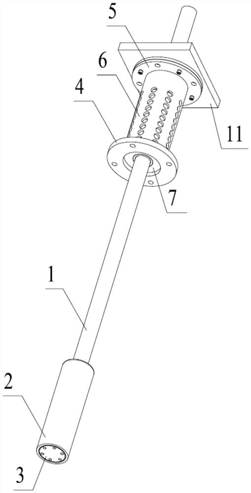
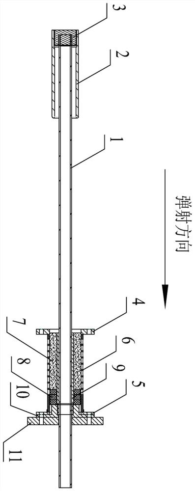
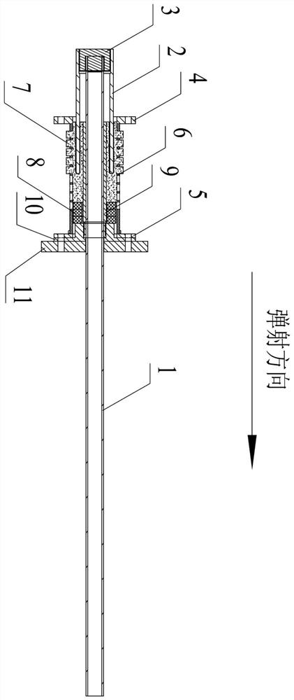
[0031] Such as figure 1 and figure 2 As shown, a momentum and energy absorbing device shared by rubber and cement includes: an actuating device, a guiding device and a buffering device; the actuating device impacts the buffering device through the guiding device, and the buffering device is provided with mastic 7 inside, and the buffering device passes through the mastic 7 The kinetic energy of the actuating device is absorbed, and the actuating device brakes by absorbing the kinetic energy through the cement 7; the side wall of the buffer device is provided with a through hole, and the cement 7 absorbs the kinetic energy and is discharged through the through hole; the actuating device includes: the inner rod 1 of the actuating device, the actuating device The outer rod 2 of the device and the adapter 3; the inner end of the outer rod 2 of the actuator is installed with the adapter 3, and the adapter 3 is fixedly connected to one end of the inner rod 1 of the actuator, and th...

Embodiment 2

[0033] Embodiment 2 is a preferred example of Embodiment 1.

[0034] Example 2

[0035] The present invention includes: an inner rod 1 of the actuating device, an outer rod 2 of the actuating device, an adapter 3, a front end plate of the outer sleeve 4, a rear end plate of the outer sleeve 5, an outer cylinder 6, cement 7, a rubber pad 8, and an inner cylinder 9. Adapter plate 10 and fixed plate 11; the inner rod 1 of the actuating device and the outer rod 2 of the actuating device are connected through the adapter 3 to form the actuating device; the outer cylinder 6 passes through the front end plate 4 of the outer sleeve and the rear end of the outer sleeve The plate 5 is fixed on the outer part, and there are several through holes on the surface of the outer cylinder 6; the inner cylinder 9 is nested in the outer cylinder 6 and fixed on the fixed plate 11 by the adapter plate 10 and the rear end plate 5 of the outer sleeve; Three ring-shaped rubber pads 8 are placed in th...


PUM


Abstract

The invention provides a momentum and energy absorption device shared by rubber and daub. The device comprises an actuating device, a guide device and a buffer device, wherein the actuating device impacts the buffer device through the guide device, the buffer device is internally provided with daub, the buffer device absorbs kinetic energy of the actuating device through the daub, and the actuating device absorbs the kinetic energy through the daub for braking; and through holes are formed in the side wall of the buffer device, and the daub absorbs the kinetic energy and then is discharged through the through holes. For the device, the braking problem of the actuating device in an ejection test is effectively solved through the buffering and guiding design of the daub -rubber pad, and during the period, all parts are not damaged by rubbing, and can be quickly reset and reused.

Description

technical field [0001] The invention relates to the field of ejection devices, in particular to a momentum and energy absorption device shared by rubber and cement. Background technique [0002] When the missile adopts the cold launch method, a corresponding actuating device is required to push the missile out of the cylinder at high speed. In order to fully study the functional performance of missiles at different ejection velocities, it is usually necessary to conduct missile ejection tests during the development and design stage. During the test, the actuating device pushes the missile forward at high speed to the set speed, the missile is separated from the actuating device, the missile continues to fly, and the actuating device needs to brake to prepare for the next test. During the braking process of the actuator, the actuator is required to brake safely, stably and reliably, without causing damage to the relevant test devices and equipment. For the existing aerodyna...

Claims


Application Information

Patent Timeline
Patent Type & Authority Applications(China)
IPC IPC(8): F15B15/22F42B35/00
CPCF15B15/226F42B35/00
Inventor 钟山王志成刘龙涛杨艳洲尚宇晴于喆
Owner SHANGHAI INST OF ELECTROMECHANICAL ENG
Why Eureka
Eureka Blog
Learn More