Hydro-electric braking system

A technology of electro-hydraulic brakes and brake master cylinders, which is applied in the direction of brakes, brake transmission devices, vehicle components, etc., can solve the problem of braking without serving pure electric vehicles, etc., and achieve small volume, small volume requirements, The effect of reducing labor intensity

Active Publication Date: 2009-06-24
BYD CO LTD
View PDF5 Cites 0 Cited by
  • Summary
  • Abstract
  • Description
  • Claims
  • Application Information

AI Technical Summary

Problems solved by technology

[0003] The purpose of the present invention is to provide an effective pure electric vehicle electro-hydraulic braking system in order to solve the braking problem of pure electric vehicles without servo vacuum

Method used


Image

  • Hydro-electric braking system

Examples


Embodiment Construction

[0017] The present invention is described in detail below in conjunction with accompanying drawing by specific embodiment:

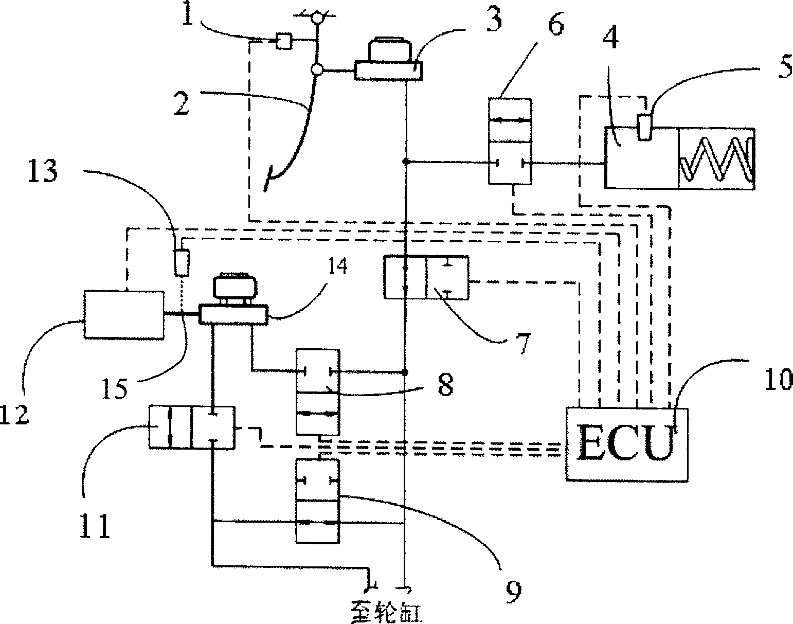
[0018] An electro-hydraulic brake system for a pure electric vehicle includes three parts, namely a brake simulation part, a brake execution part and an ECU control part. Such as figure 1 Shown:

[0019] The brake simulation part includes a normally open contact switch 1 , a brake pedal 2 , a first brake master cylinder 3 , a brake simulator 4 , a hydraulic pressure sensor 5 and a normally closed solenoid valve 6 . The brake pedal 2 withstands the electric shock switch 1 and is connected with the first brake master cylinder 3. The brake simulator 4 is equipped with a hydraulic pressure sensor 5, and the first normally closed solenoid valve 6 is arranged between the first brake master cylinder 3 and the first brake master cylinder 3. Between brake simulator 4.

[0020] The brake execution part includes a first normally open solenoid valve 7, a second n...


PUM


Abstract

The invention relates to an electro-hydraulic braking system, which includes a brake pedal and a first brake master cylinder connected with the brake pedal, and is characterized in that it also includes a motor, a push rod, a second brake master cylinder, and an ECU control unit , the motor is connected to the second brake master cylinder through the control push rod, and the ECU control unit receives the brake signal from the brake pedal to control the motor to act. The invention uses a linear motor to drive the piston movement of the brake master cylinder to achieve the purpose of braking, retains the traditional vacuum booster hydraulic brake system, cancels the vacuum booster, and changes the double cylinder brake master cylinder into a single cylinder, so that it is not affected. Serving the limitation of vacuum, it can be used in modern pure electric vehicles, requiring very little manpower, reducing manpower fatigue and improving driver safety.

Description

【Technical field】 [0001] The invention relates to an electro-hydraulic braking system for automobiles. 【Background technique】 [0002] Vacuum boosters are widely used as brake boosters in automobiles. They mainly use the vacuum at the engine throat to help the driver manipulate the brake pedal, push the brake hydraulic master cylinder to brake by manpower, and use the engine intake of traditional fuel vehicles to , Vacuum servo brake. Due to the bulky vacuum booster, the layout of the vehicle structure is subject to many restrictions, and there is no servo vacuum in the pure electric vehicle, the driver's manpower required for braking is high, and he is prone to fatigue. 【Content of invention】 [0003] The object of the present invention is to provide an effective electro-hydraulic braking system for pure electric vehicles to solve the braking problem of pure electric vehicles without servo vacuum. [0004] In order to achieve the above object, the present invention prop...

Claims


Application Information

Patent Timeline
Patent Type & Authority Patents(China)
IPC IPC(8): B60T13/74
Inventor 王国保胡庚伟宋佑川王汝辉
Owner BYD CO LTD
Why Eureka
Try Eureka