A photoelectric CT hybrid isolation transformer differential protection system and method

An isolation transformer and differential protection technology, applied in the direction of measuring electrical variables, emergency protection circuit devices, instruments, etc., can solve the problems of differential protection misoperation, transformer excitation inrush braking, etc., to achieve excitation inrush braking, easy Realize and upgrade simple effects

Active Publication Date: 2017-07-14
STATE GRID CORP OF CHINA +1
View PDF6 Cites 0 Cited by
  • Summary
  • Abstract
  • Description
  • Claims
  • Application Information

AI Technical Summary

Problems solved by technology

Discontinuous corner braking will also cause differential protection misoperation due to discontinuous corner deformation
[0005] Therefore, a new method is needed to identify the excitation inrush current, so as to finally solve the problem of excitation inrush current braking of transformer differential protection

Method used


Image

  • A photoelectric CT hybrid isolation transformer differential protection system and method
  • A photoelectric CT hybrid isolation transformer differential protection system and method
  • A photoelectric CT hybrid isolation transformer differential protection system and method

Examples


Embodiment 1

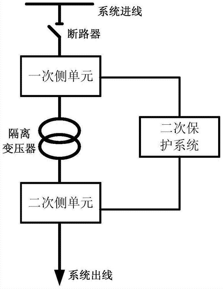
[0057] Such as figure 1 , a photoelectric CT hybrid isolation transformer differential protection system, the system includes a primary side unit, an isolation transformer, a secondary side unit, a secondary protection system, a system incoming line, a system outgoing line, and a circuit breaker; a system incoming line and a system The outgoing lines are respectively connected to the primary side and the secondary side of the isolation transformer through the primary side unit and the secondary side unit. Both the primary side unit and the secondary side unit are connected to the secondary protection system. between side units.

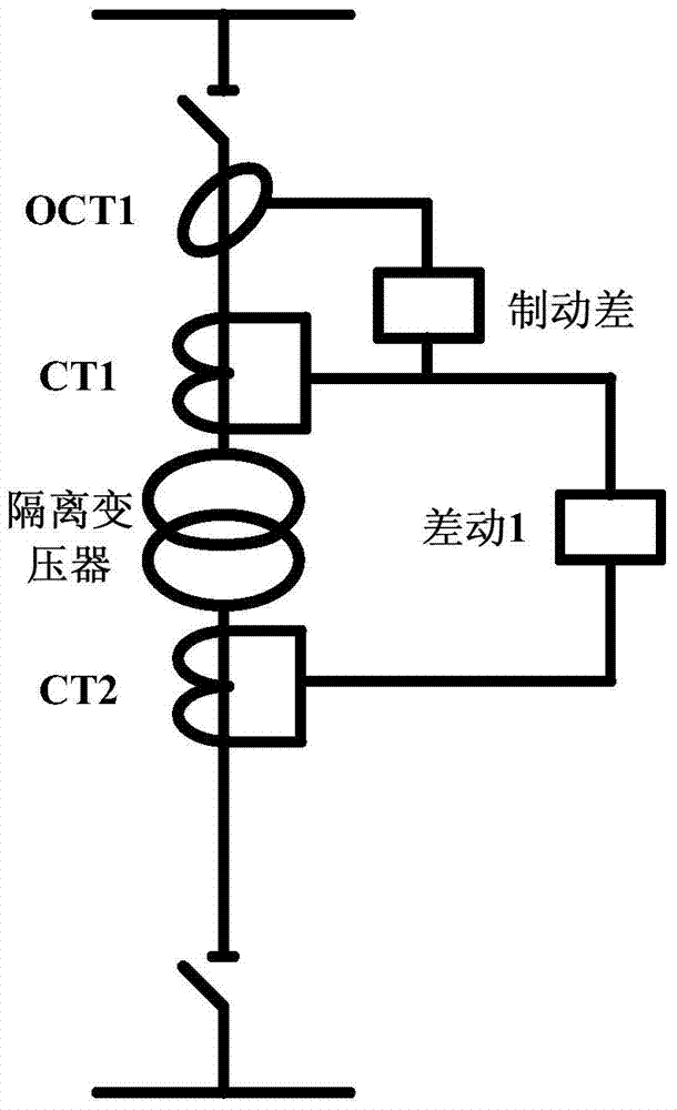
[0058] The primary side unit includes the first all-fiber optic current transformer OCT1 and the first electromagnetic current transformer CT1; the first all-fiber optic current transformer OCT1 is used to measure the current of electrical equipment, and is wound on the primary side of the isolation transformer through optical fibers On the incoming ...

Embodiment 2

[0069] Such as Figure 4 , a photoelectric CT hybrid isolation transformer differential protection system, the system includes a primary side unit, an isolation transformer, a secondary side unit, a secondary protection system, a system incoming line, a system outgoing line, and a circuit breaker; a system incoming line and a system The outgoing lines are respectively connected to the primary side and the secondary side of the isolation transformer through the primary side unit and the secondary side unit. Both the primary side unit and the secondary side unit are connected to the secondary protection system. between side units.

[0070] The primary side unit includes the first all-fiber optic current transformer OCT1 and the first electromagnetic current transformer CT1; the first all-fiber optic current transformer OCT1 is used to measure the current of electrical equipment, and is wound on the primary side of the isolation transformer through optical fibers On the incoming...

Embodiment 3

[0081] Such as Figure 6 , a photoelectric CT hybrid isolation transformer differential protection system, the system includes a primary side unit, an isolation transformer, a secondary side unit, a secondary protection system, a system incoming line, a system outgoing line, and a circuit breaker; a system incoming line and a system The outgoing lines are respectively connected to the primary side and the secondary side of the isolation transformer through the primary side unit and the secondary side unit. Both the primary side unit and the secondary side unit are connected to the secondary protection system. between side units.

[0082] The primary side unit includes the first all-fiber optic current transformer OCT1 and the first electromagnetic current transformer CT1; the first all-fiber optic current transformer OCT1 is used to measure the current of electrical equipment, and is wound on the primary side of the isolation transformer through optical fibers On the incoming...


PUM


Abstract

The invention provides a photoelectric CT mixed isolation transformer differential protection system and method. The system includes a primary side unit, an isolation transformer, a secondary side unit, a secondary protection system, a system incoming line, a system outgoing line, and a circuit breaker; the system incoming line and the system outgoing line are respectively connected to the primary side and secondary side of the isolation transformer through the primary side unit and the secondary side unit. Both the primary side unit and the secondary side unit are connected to the secondary protection system, and the circuit breaker is located at the and primary side unit. The invention provides a photoelectric CT hybrid isolation transformer differential protection system and method. The system has compact structure, strong anti-interference ability, and high reliability. It can accurately judge the excitation inrush current of the transformer to brake the differential protection, and the application range covers All transformer differential protection systems.

Description

technical field [0001] The invention relates to the technical field of transformer protection, in particular to a differential protection system and method for an isolation transformer mixed with photoelectricity and CT. Background technique [0002] With the continuous development of the power system, the application of large-capacity transformers is becoming more and more extensive, and higher requirements are put forward for the reliability and quickness of transformer protection. Transformer differential protection has been widely accepted due to its good selectivity and rapidity. Pay attention to. As the key technology of power transformer relay protection, differential protection is widely used in traditional analog protection and new microcomputer protection. Long-term operation experience shows that the main problem of current transformer differential protection is still focused on the identification of internal faults and excitation inrush current. When a magnetiz...

Claims


Application Information

Patent Timeline
Patent Type & Authority Patents(China)
IPC IPC(8): H02H7/045G01R31/00
Inventor 蔡林海荆平陈硕陈国富王江波蒋晓春赵国亮
Owner STATE GRID CORP OF CHINA
Why Eureka
Try Eureka