A vehicle component structure and a motor vehicle

A technology for vehicle parts and components, which is applied to vehicle parts, motor vehicles, road vehicles, etc., can solve the problem of increasing the total weight of the vehicle, and achieve the effects of saving construction space, low cost, and low consumption.

Active Publication Date: 2019-04-26
DR ING H C F PORSCHE AG
View PDF7 Cites 0 Cited by
  • Summary
  • Abstract
  • Description
  • Claims
  • Application Information

AI Technical Summary

Problems solved by technology

In addition, the weight or gross vehicle weight usually increases with the number of necessary components and the number of wiring to these components

Method used


Image

  • A vehicle component structure and a motor vehicle
  • A vehicle component structure and a motor vehicle
  • A vehicle component structure and a motor vehicle

Examples


Embodiment Construction

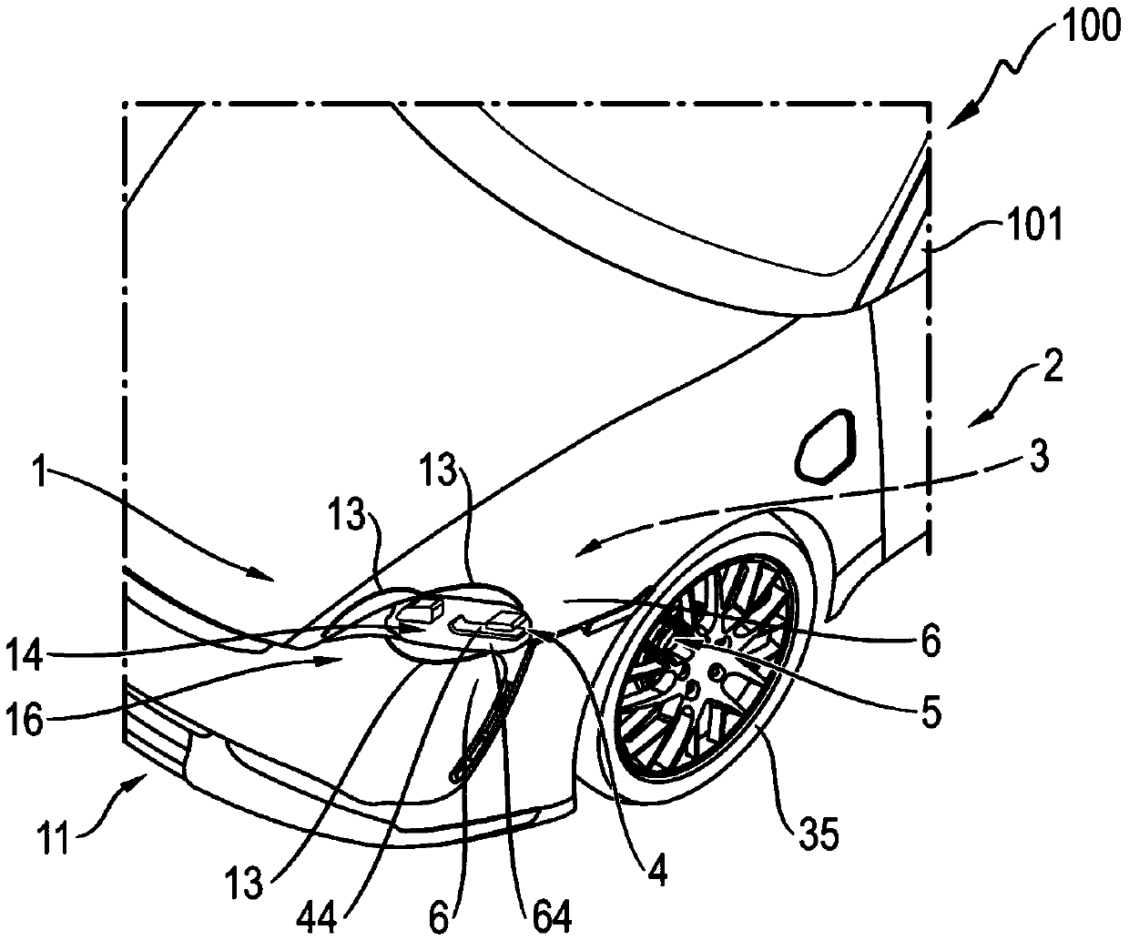
[0054] figure 1 A vehicle component arrangement 1 according to the invention is shown, which is installed here in a motor vehicle 100 in the form of a passenger vehicle (Pkw) 101 . Passenger car 101 is, for example, an electric vehicle or is driven by an internal combustion engine.

[0055] The motor vehicle 100 is here shown in a cutaway perspective from obliquely above, so that the left-hand region of the vehicle front 11 can be seen particularly easily.

[0056] The vehicle component structure includes a cooling device 2 for cooling the vehicle component by means of a cooling air flow. For this purpose, the cooling device 2 has an air duct system 3 which is provided here with an inlet opening 13 in the region of the vehicle front 11 . In this case, that part of the air duct system 3 adjoining the inlet opening 13 is arranged invisibly in the interior of the vehicle 100 or behind one or more housing components 6 .

[0057] Three possible arrangements of the inlet openings...


PUM


Abstract

The invention relates to a vehicle component structure (1) including a cooling device (2). The cooling device is provided with an air passage system (3) for guiding a cooling air stream. The air passage system has an inlet opening (13). The cooling air stream can be conveyed through the air passage system (3) to at least one lighting lamp device (4) and at least one brake device (5), and therefore, waste heat of the lighting lamp device and the brake device can be discharged by the cooling air stream.

Description

technical field [0001] The invention relates to a vehicle component structure with at least one cooling device having at least one air duct system for guiding a cooling air flow and comprising at least one inlet opening. Background technique [0002] Operation of a motor vehicle generally causes certain components to heat up. To guarantee optimum functionality and durability of these components, cooling or heat dissipation is often necessary. [0003] Here, the cooling requirements are increasing. In general, the smallest possible construction space and weight should be required. Furthermore, care must be taken, especially in the context of vehicle electrification, that the cooling does not have a detrimental effect on the overall energy management of the vehicle. [0004] Often, additional components, such as fans, are installed for cooling, which is time consuming, costly and prone to failure. Constructing spatial concepts can often only be achieved through stylistic c...

Claims


Application Information

Patent Timeline
Patent Type & Authority Applications(China)
IPC IPC(8): B60T5/00F21V29/50
CPCF21V29/502B60T5/00F21S45/43F16D65/847B60Y2200/11B60Y2200/91F21V29/50
Inventor J·奥斯特塔格E·格茨
Owner DR ING H C F PORSCHE AG
Why Eureka
Try Eureka