Impact grade adjustable hydraulic jackdrill based on vibration impact

A hydraulic rock drill, an adjustable technology, is applied in the directions of impact drilling, reciprocating drilling rig, non-rotational vibration suppression, etc., and can solve the problems of damage to the rock drill rod and connecting components, high use cost, and repeated drilling. To achieve the effect of reducing the probability of sticking, saving investment costs, and ensuring the effect of rock drilling

Active Publication Date: 2019-07-12
HUNAN UNIV OF ARTS & SCI
View PDF11 Cites 1 Cited by
  • Summary
  • Abstract
  • Description
  • Claims
  • Application Information

AI Technical Summary

Problems solved by technology

[0006] The object of the present invention is to provide a shock level adjustable hydraulic rock drill based on vibration and shock, to solve the above-mentioned background technology, because most of the rock structure strength is relatively high, so it is necessary to use a shock absorbing structure to control the operation of the rock drilling rod from the inside. The shock-absorbing operation is performed, but the existing rock drills cannot conveniently adjust the leveling of the rock drilling rod, and long-term use will easily cause damage to the rock drilling rod and the connecting components; most of the existing rock drilling machines are driven by motor gear meshing , to drive the rock drilling rod to rotate at the same time when it reciprocates, but the design of this type of structure has a high cost and is inconvenient to use; in order to solve the stuck drill phenomenon, the existing rock drills mostly use a hydraulic return mechanism at the bottom of the rock drill. The drill tail part of the rock drill is released from the rock, but the root cause of the clamping phenomenon and the accumulation of a large number of broken rocks in the drilling hole has not been solved, so the problem of multiple clamping phenomena is prone to occur

Method used


Image

  • Impact grade adjustable hydraulic jackdrill based on vibration impact
  • Impact grade adjustable hydraulic jackdrill based on vibration impact
  • Impact grade adjustable hydraulic jackdrill based on vibration impact

Examples


Embodiment Construction

[0028] The following will clearly and completely describe the technical solutions in the embodiments of the present invention with reference to the accompanying drawings in the embodiments of the present invention. Obviously, the described embodiments are only some, not all, embodiments of the present invention. Based on the embodiments of the present invention, all other embodiments obtained by persons of ordinary skill in the art without making creative efforts belong to the protection scope of the present invention.

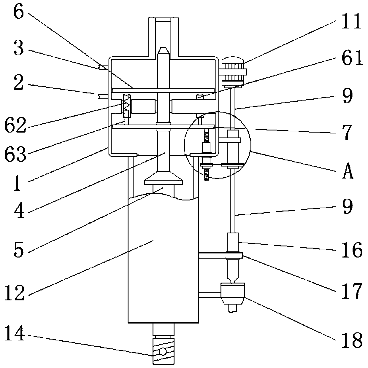
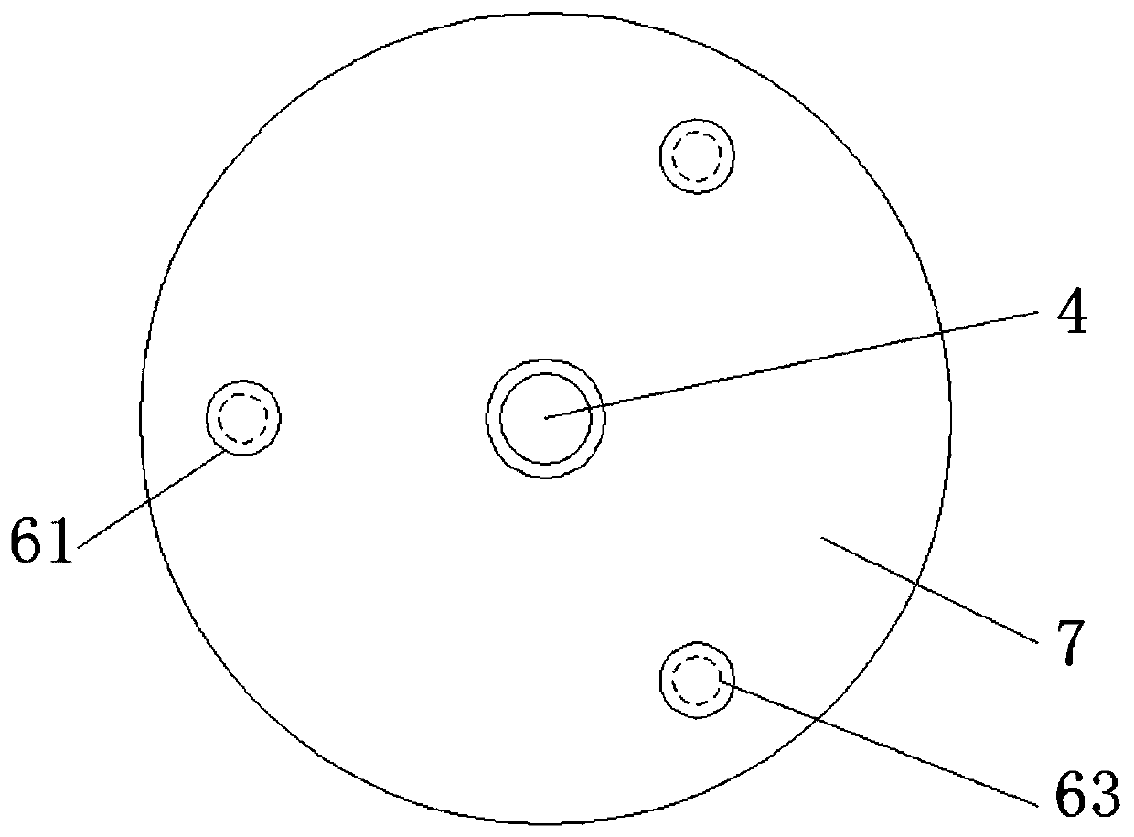
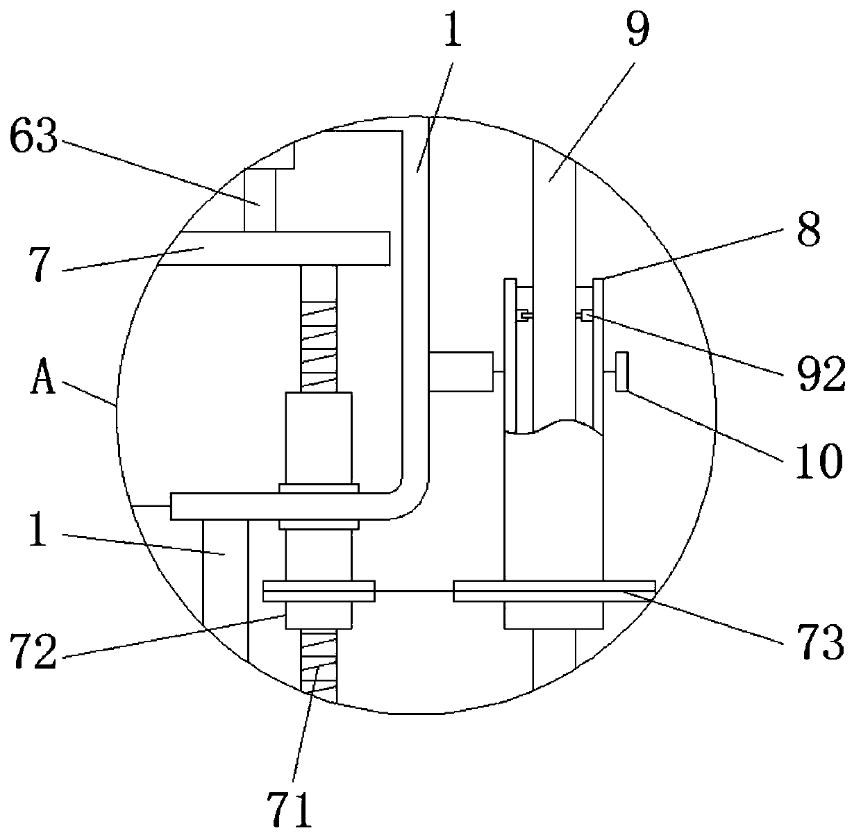
[0029] see Figure 1-7, the present invention provides a technical solution: a hydraulic rock drill based on vibration and shock, including a power box 1, a first oil inlet 2, a second oil inlet 3, a piston rod 4, a rock drilling rod 5, Valve plate 6, sleeve 61, spring 62, damping rod 63, adjusting plate 7, adjusting rod 71, connecting cylinder 72, pulley 73, outer cylinder 8, rotating shaft 9, first pawl 91, first ratchet 92, The first bearing seat 10, the m...


PUM


Abstract

The invention discloses an impact grade adjustable hydraulic jackdrill based on vibration impact. The impact grade adjustable hydraulic jackdrill comprises a power box, a first oil inlet and a secondoil inlet, wherein the first oil inlet and the second oil inlet are formed in the side of the power box; and a connecting pipe is installed on the shell wall of the shell, a rotating drum is arrangedon the side of the connecting pipe, the rotating drum is rotatably connected with the shell through a second bearing seat, the bottom end of the rotating drum is installed on a slag discharging box, the top end of the rotating drum is connected with the bottom end of a rotating shaft, and the slag discharging box is fixedly connected with the shell. The impact grade adjustable hydraulic jackdrillbased on vibration impact can conveniently adjust the impact grade of a rock drill rod, use is more convenient, the jackdrill can rotate simultaneously by utilizing the linear movement of the rock drill rod, and thus the investment cost of equipment such as motor parts is saved; and broken rocks are cleaned in real time while rock drilling, and the stuck probability of a drill rod is reduced to the greatest extent.

Description

technical field [0001] The invention relates to the technical field of rock drills, in particular to a vibration-shock-based adjustable hydraulic rock drill. Background technique [0002] Rock drilling machine, as the name suggests, is a kind of mechanical equipment for hammering and chiseling rocks. Due to its special function, this type of equipment is generally installed at the end of the vertical arm of locomotives such as excavators, so that it can be used to excavate The machine equipment drives the heavy rock drilling machine, and when the rock drilling machine is in use, the hydraulic principle is used to drive the rock drilling rod to move back and forth, but the existing hydraulic rock drilling machine has the following problems when it is used for specific rock drilling: [0003] 1. Due to the high strength of most rock structures, it is necessary to use a shock-absorbing structure to cushion the operation of the rock drilling rod from the inside. However, the exi...

Claims


Application Information

Patent Timeline
Patent Type & Authority Applications(China)
IPC IPC(8): E21B1/26E21B21/00F16F15/04
CPCE21B1/02E21B21/00F16F15/04
Inventor 李叶林
Owner HUNAN UNIV OF ARTS & SCI
Why Eureka
Try Eureka